BRAKE SYSTEM Vacuum Warning Buzzer Circuit
DESCRIPTION
The vacuum warning switch is installed in the vacuum reservoir. If the vacuum in the vacuum reservoir drops, the vacuum warning switch turns on and the vacuum warning buzzer sounds.
When the parking brake is applied, the parking brake switch cut off the power supply to the buzzer circuit.
If the vehicle is equipped with a DPF system, the ECM blinks the DPF indicator light and sounds the vacuum warning buzzer intermittently when the ECM determines that a specified amount of carbon has accumulated in the exhaust DPF filter.
WIRING DIAGRAM

INSPECTION PROCEDURE
Note
The following inspections are performed with the parking brake released. Park the vehicle on a level surface and use chocks to secure the vehicle.
PROCEDURE
-
CHECK VACUUM WARNING BUZZER
-
Depress the brake pedal several times with the engine stopped to release the vacuum in the booster and vacuum reservoir tank.
-
Depress the brake pedal and release the parking brake.
-
Turn the ignition switch to the ON position (do not start the engine). Check that the vacuum warning buzzer sounds.
-
Start the engine to create vacuum. Check that the vacuum warning buzzer stops sounding.
Result Result Proceed to The buzzer sounds when the ignition switch is turned to the ON position and stops after the engine is started. A The buzzer does not sound. B The buzzer does not stop sounding. C Tech Tips
-
The vacuum warning buzzer sounds continuously to inform the driver that the vacuum is insufficient for brake boost.
-
If the buzzer sounds intermittently and the DPF indicator light blinks after the engine is started, operate the DPF switch to combust the carbon in the exhaust DPF filter.
-
B 
CHECK HARNESS AND CONNECTOR (BUZZER POWER SOURCE) Click here
C
CHECK VACUUM WARNING SWITCH Click here
A 
END
-
-
CHECK HARNESS AND CONNECTOR (BUZZER POWER SOURCE)
-
Release the parking brake and turn the ignition switch to the ON position.
-

Measure the voltage according to the value(s) in the table below.
Note
Measure the voltage from the backside of the connector with the vehicle harness connector connected to the buzzer.
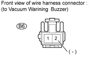
Standard voltage Tester Connection Condition Specified Condition B6-1 - Body ground Ignition switch ON and parking brake OFF 22 to 27 V
NG
INSPECT PARKING BRAKE SWITCH Click here
OK 
-
-
INSPECT VACUUM WARNING BUZZER
-
Release the parking brake and turn the ignition switch to the ON position.
-
Connect terminal B6-2 of the vacuum warning buzzer and body ground. Check if the buzzer sounds.
Note
Perform this inspection from the backside of the connector with the vehicle harness connector connected to the buzzer.
OK The buzzer sounds.
NG 
REPLACE VACUUM WARNING BUZZER Click here
OK
-
-
CHECK HARNESS AND CONNECTOR (VACUUM WARNING SWITCH POWER SOURCE)
-
Disconnect the connector from the vacuum warning switch on the vacuum reservoir tank.
-
Release the parking brake and turn the ignition switch to the ON position.
-
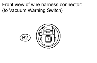
Measure the voltage according to the value(s) in the table below.
Standard voltage Tester Connection Condition Specified Condition B2-1 - Body ground Ignition switch ON and parking brake OFF 22 to 27 V
NG
REPAIR OR REPLACE HARNESS OR CONNECTOR (VACUUM WARNING BUZZER - VACUUM WARNING SWITCH)
OK
REPLACE VACUUM WARNING SWITCH Click here
-
-
INSPECT PARKING BRAKE SWITCH
-
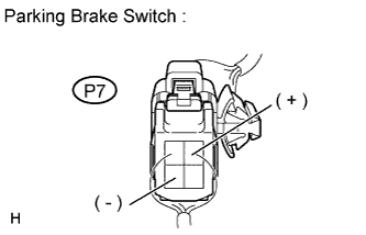
Measure the voltage according to the value(s) in the table below.
Note
Measure the resistance from the backside of the connector with the vehicle harness connector connected to the switch.
Standard resistance Tester Connection Condition Specified Condition P7-1 - P7-4 Release the parking brake Below 1 Ω
NG
REPLACE PARKING BRAKE SWITCH
OK
-
-
CHECK HARNESS AND CONNECTOR (PARKING BRAKE SWITCH)
-
Disconnect the parking brake switch connector (P7).
-
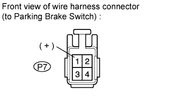
Measure the voltage according to the value(s) in the table below.
Standard voltage Tester Connection Condition Specified Condition P7-1 - Body ground Ignition switch ON 22 to 27 V
NG
REPAIR OR REPLACE HARNESS OR CONNECTOR (PARKING BRAKE SWITCH POWER SOURCE CIRCUIT)
OK
REPAIR OR REPLACE HARNESS OR CONNECTOR (PARKING BRAKE SWITCH - VACUUM WARNING BUZZER)
-
-
CHECK VACUUM WARNING SWITCH
-
Disconnect the connector from the vacuum warning switch (B2) on the vacuum reservoir tank. Check that the vacuum warning buzzer stops sounding.
OK The buzzer stops sounding due to the disconnection of the connector.
NG
CHECK HARNESS AND CONNECTOR Click here
OK
-
-
CHECK VACUUM
-
Visually check the vacuum piping for disconnection, cracks, or damage.
OK The vacuum piping is not disconnected, cracked, or damaged -
Install a vacuum gauge between the brake booster and the vacuum reservoir tank, and measure the vacuum.
OK 24 kPa (180 mmHg) or higher (vacuum at which the vacuum warning switch operates)
NG
CHECK VACUUM SOURCE AND HOSES
OK
REPLACE VACUUM WARNING SWITCH Click here
-
-
CHECK HARNESS AND CONNECTOR
-
Disconnect the vacuum warning buzzer connector (B6), vacuum warning switch connector (B2), and ECM connector (E23).
-
Measure the resistance according to the value(s) in the table below.
Standard resistance Tester Connection Condition Specified Condition B6-2 - Body ground Always 1 MΩ or higher
NG
REPAIR OR REPLACE HARNESS OR CONNECTOR
OK
-
-
CHECK ECM (PMB)
-
Connect the vacuum warning buzzer connector (B6), vacuum warning switch connector (B2), and ECM connector (E23).
-
Release the parking brake and turn the ignition switch to the ON position.
-
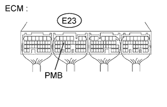
Measure the voltage according to the value(s) in the table below.
Note
Measure the voltage from the backside of the connector with the vehicle harness connector connected to the ECM.
Standard voltage Tester Connection Condition Specified Condition E23-16 - Body ground Ignition switch ON and parking brake OFF 22 to 27 V
NG
REPLACE ECM Click here
OK
REPLACE VACUUM WARNING BUZZER Click here
-