CLUTCH PEDAL STROKE SENSOR INSTALLATION

-
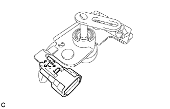
INSTALL CLUTCH PEDAL STROKE SENSOR ASSEMBLY
-
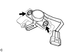
Temporarily install the clutch pedal stroke sensor assembly with the 2 nuts.
Tech Tips
Tighten the 2 nuts after adjusting the clutch pedal stroke sensor assembly.
-
Engage the clamp.
-
-
INSTALL CLUTCH PEDAL BRACKET
-
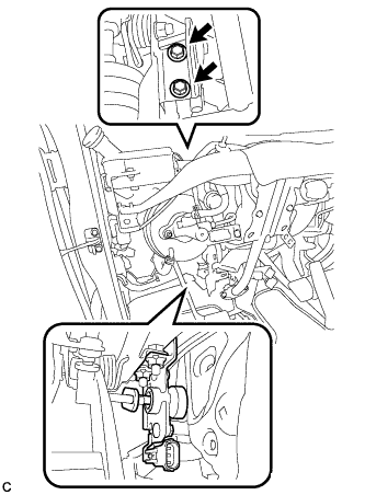
Install the clutch pedal bracket with the 2 bolts.
- Torque:
- 15 N*m { 153 kgf*cm, 11 ft.*lbf }
-
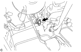
Connect the connector.
-
-
INSTALL INSTRUMENT PANEL
Tech Tips
Refer to the instructions for Installation of the instrument panel.
-
ADJUST CLUTCH PEDAL STROKE SENSOR ASSEMBLY
-
Connect the intelligent tester to the DLC3.
-
Turn the ignition switch to ON.
-
Turn the intelligent tester on.
-
Read the values of the clutch pedal stroke sensor assembly in the ECU data on the intelligent tester display.
-
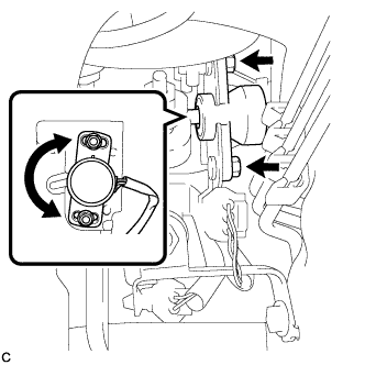
Turn the clutch pedal stroke sensor assembly slowly to the right and left to adjust the output voltage to the standard values.
Measurement Condition Standard Value (V) Diagnostic Note Ignition switch ON
Clutch pedal released
0.5 to 1.0 When the voltage is 0.15 V or less, a DTC is output. Ignition switch ON
Clutch pedal depressed
2.6 to 4.5 When the voltage is 4.85 V or more, a DTC is output. -
Tighten the 2 nuts.
- Torque:
- 8.5 N*m { 87 kgf*cm, 75 in.*lbf }
-
Disconnect the intelligent tester from the DLC3.
-
-
CLUTCH PEDAL STROKE SENSOR ZERO POINT CALIBRATION
-
If the clutch pedal stroke sensor has been replaced, perform clutch pedal stroke sensor zero point calibration and release position calibration Click here.
-