CLUTCH PEDAL STROKE SENSOR INSPECTION

-
INSPECT CLUTCH PEDAL STROKE SENSOR ASSEMBLY
-
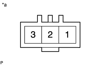
Text in Illustration *a Component without harness connected
(Clutch Pedal Stroke Sensor Assembly)
Measure the resistance according to the value(s) in the table below.
Standard Resistance Tester Connection Condition Specified Condition 1 (C+B) - 3 (C-S) Always 1.6 to 2.4 kΩ If the result is not as specified, replace the clutch pedal stroke sensor assembly.
-
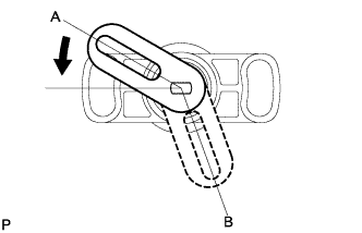
Measure the resistance according to the value(s) in the table below.
Standard Resistance Tester Connection Condition Specified Condition 1 (C+B) - 2 (CSS) Sensor arm at position A 0.32 to 0.48 kΩ Sensor arm at position B 1.92 to 2.88 kΩ -
Measure the resistance between terminal 1(C+B) and 2(CSS) while moving the sensor arm from position A to position B.
Standard The resistance continuously changes.
-