REAR DISC BRAKE INSTALLATION

-
INSTALL REAR SKID CONTROL ROTOR
-
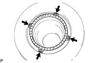
Using a hexagon wrench (5 mm), install the rear skid control rotor.
- Torque:
- 14 N*m { 143 kgf*cm, 10 ft.*lbf }
-
-
INSTALL REAR DISC
-
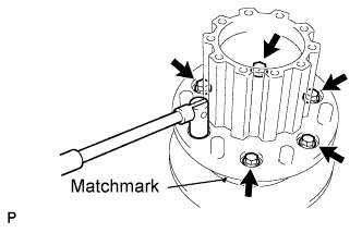
Align the matchmarks of the brake disc and the rear axle hub and then install them with the 6 bolts.
- Torque:
- 200 N*m { 2040 kgf*cm, 147 ft.*lbf }
-
-
INSTALL REAR AXLE HUB AND DISC ASSEMBLY
-
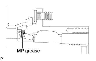
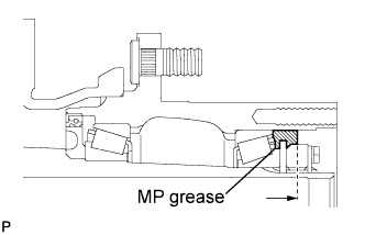
Fill MP grease so that there should be no gap in the space between the oil seal and rear axle hub inner bearing.
-
Clean the rear axle hub and disc assembly contact surface of the rear axle housing. Apply a light coat of grease to the contact surface.
-
Install the rear axle hub and disc assembly on the rear axle housing.
-
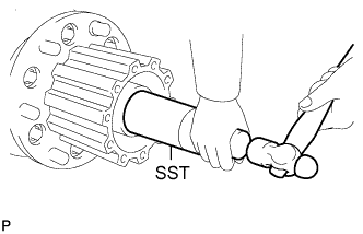
Using SST and a hammer, tap in the outer bearing to the rear axle housing.
- SST
- 09214-76011
Note
Be careful not to damage the outer bearing.
-
-
INSTALL REAR AXLE BEARING LOCK NUT
-
Install the lock nut plate.
-
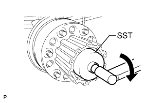
Using SST, turn the rear axle hub and disc assembly to tighten the rear axle housing lock nut.
- SST
- S0983-99401
- Torque:
- 539 N*m { 5500 kgf*cm, 397 ft.*lbf }
-
-
ADJUST PRELOAD
-
Using a plastic hammer, tap the rear axle hub. Turn the rear wheel hub in both directions 2 or 3 times to settle the bearing into position.
-
Using SST, loosen the bearing lock nut until the rear axle hub can be lightly turned.
- SST
- S0983-99401
Tech Tips
The bearing lock nut should not be loosened enough to be turned by hand.
-
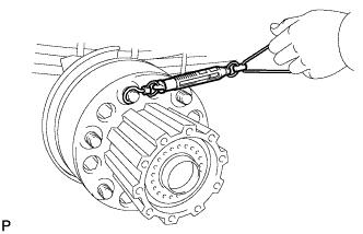
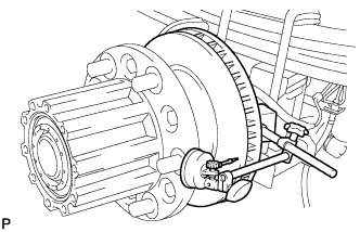
Using a spring tension gauge, measure the turning torque of the rear axle hub.
Torque 35 to 53 N (3.6 to 5.4 kgf, 7.9 to 11.9 lbf) Note
-
Make sure that there is no brake drag.
-
After adjusting the rear axle bearing lock nut, be sure to tap the rear axle hub with a plastic hammer to settle the bearing into position.
-
Measure the turning torque in both clockwise and counterclockwise directions.
-
-
-
INSTALL REAR AXLE LOCK NUT PLATE
-
Install the lock nut plate.
-
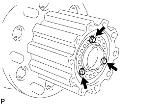
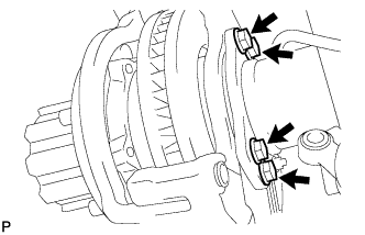
Secure the lock nut plate and rear axle bearing lock nut with the 3 bolts.
- Torque:
- 9.6 N*m { 98 kgf*cm, 85 in.*lbf }
Note
Align the bolt installation holes on the lock nut plate and rear axle bearing lock nut by tightening the lock nut by the minimum possible amount.
-
-
FILL UP GREASE
-
Fill the rear axle hub with grease up to the center of the thickness of the lock nut.
-
-
INSTALL REAR AXLE SHAFT OIL SEAL
(See Pub. No. RM1008E, page 30-75)
-
INSTALL REAR AXLE SHAFT
(See Pub. No. RM1008E, page 30-75)
-
INSPECT DISC RUNOUT
-
Using a dial indicator, measure the disc runout 10 mm (0.39 in.) away from the outer edge of the disc.
Maximum disc runout 0.1 mm (0.0039 in.) Tech Tips
If the runout exceeds the maximum value, change the installation positions of the disc and axle so that the runout will become minimal. If the runout exceeds the maximum even when the installation positions are changed, check the bearing play in the axial direction and the axle hub runout. If the bearing play and the axle hub runout are normal and if the disc thickness is not within the specified range, shave the disc. If the disc thickness is less than the minimum, replace the disc.
-
-
INSTALL REAR DISC BRAKE CYLINDER MOUNTING
-
Install the rear disc brake cylinder mounting with the 4 bolts.
- Torque:
- 265 N*m { 2700 kgf*cm, 195 ft.*lbf }
-
-
INSTALL REAR DISC BRAKE BUSHING DUST BOOT
-
Apply lithium soap base glycol grease to the seal surface of 2 new rear disc brake bushing dust boots. Click here
-
Install the 2 rear disc brake bushing dust boots to the rear disc brake cylinder mounting.
-
-
INSTALL REAR DISC BRAKE CYLINDER SLIDE PIN
-
Apply lithium soap base glycol grease to the sliding part and the seal surface of the rear disc brake cylinder slide pin. Click here
-
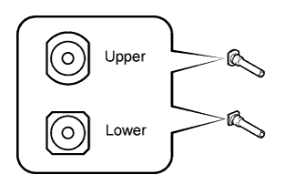
Install the rear disc brake cylinder slide pin to the rear disc brake cylinder mounting as shown in the illustration.
-
-
INSTALL REAR DISC BRAKE PAD SUPPORT PLATE
-
Install the 4 pad support plates to the rear disc brake cylinder mounting.
-
-
INSTALL REAR DISC BRAKE ANTI-SQUEAL SHIM
Note
When replacing worn pads, the anti-squeal shims must be replaced together with the pads.
-
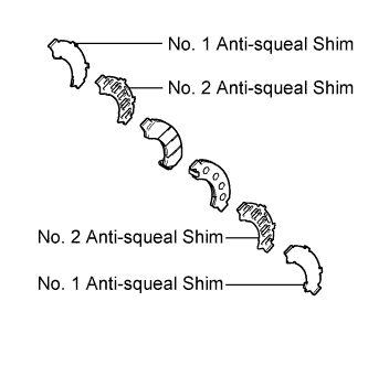
Install the 2 No. 2 anti-squeal shims and 2 No. 1 anti-squeal shims to each pad.
-
-
INSTALL REAR DISC BRAKE PAD
-
Install the 2 brake pads to the rear disc brake cylinder mounting.
-
-
INSTALL REAR DISC BRAKE CYLINDER ASSEMBLY
-

Install the rear disc brake cylinder assembly with the 2 bolts.
- Torque:
- 125 N*m { 1270 kgf*cm, 92 ft.*lbf }
-
Connect the flexible hose with the union bolt and 2 new gaskets.
- Torque:
- 31 N*m { 316 kgf*cm, 23 ft.*lbf }
-
-
FILL RESERVOIR WITH BRAKE FLUID
(See Pub. No. RM1008E, page 32-4)
-
BLEED BRAKE LINE
(See Pub. No. RM1008E, page 32-4)
-
CHECK FLUID LEVEL IN RESERVOIR
(See Pub. No. RM1008E, page 32-4)
-
INSPECT FOR BRAKE FLUID LEAK
(See Pub. No. RM1008E, page 32-4)
-
INSTALL REAR WHEEL
- Torque:
- 515 N*m { 5250 kgf*cm, 380 ft.*lbf }
-
INSPECT ABS SPEED SENSOR SIGNAL