BRAKE ACTUATOR INSTALLATION

-
INSTALL BRAKE ACTUATOR WITH BRACKET
-
Engage the guide and install the brake actuator with bracket with the 2 bolts.
- Torque:
- 34 N*m { 342 kgf*cm, 25 ft.*lbf }
Note
Do not damage the brake lines or wire harness.
-
Install the bolt.
- Torque:
- 76 N*m { 775 kgf*cm, 56 ft.*lbf }
-
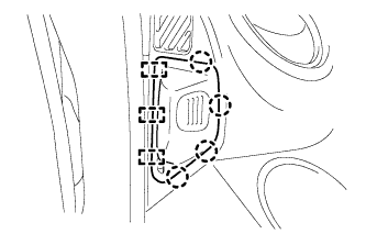
Using a 10 mm and 12 mm union nut wrench, connect the 6 brake tubes to the brake actuator assembly.
- Torque:
- Flare Nut 10 mm
- 15 N*m { 155 kgf*cm, 11 ft.*lbf }
- Flare Nut 12 mm
- 24 N*m { 245 kgf*cm, 18 ft.*lbf }
Note
Use the formula to calculate special torque values for situations where a union nut wrench is combined with a torque wrench Click here.
-

Connect the brake actuator connector.
Note
-
Make sure that the actuator connector can be connected smoothly. Do not allow entry of water, oil or dirt.
-
Make sure that the connector is locked securely.
-
-
-
CONNECT CABLE TO NEGATIVE BATTERY TERMINAL
Note
When disconnecting the cable, some systems need to be initialized after the cable is reconnected Click here.
-
REMOVE OIL RESERVOIR TANK COVER LH
-
Disengage the 4 claws and 3 guides and remove the oil reservoir tank cover LH.
-
-
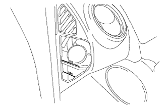
REMOVE LOWER INSTRUMENT PANEL FINISH PANEL SUB-ASSEMBLY RH
-
FILL RESERVOIR WITH BRAKE FLUID
-
Fill the reservoir with brake fluid.
Fluid SAE J1703 or FMVSS No. 116 DOT 3 Note
Add brake fluid to keep the level between the MIN and MAX lines of the reservoir while bleeding the brakes.
-
-
BLEED MASTER CYLINDER
Tech Tips
If the master cylinder has been disassembled or if the reservoir becomes empty, bleed the air from the master cylinder.
-

Using a 12 mm union nut wrench, disconnect the 2 brake tubes from the master cylinder.
-
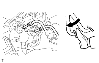
Slowly depress the brake pedal and hold it there (Step A).
-

Block the outer holes with your fingers, and release the brake pedal (Step B).
-
Repeat step A and B 3 or 4 times.
-
Using a 12 mm union nut wrench, connect the 2 brake tubes to the master cylinder.
- Torque:
- 24 N*m { 245 kgf*cm, 18 ft.*lbf }
Note
Use the formula to calculate special torque values for situations where a union nut wrench is combined with a torque wrench Click here.
-
-
BLEED BRAKE LINE
Note
-
Make sure the vehicle is secured in place and cannot move.
-
Make sure the ignition switch is off before bleeding the brake system.
-
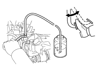
Connect the vinyl tube to the bleeder plug.
-
Depress the brake pedal 3 times, and then hold down the brake pedal. (Procedure 1)
-
Loosen the bleeder plug at least 90° so that brake fluid and air begin to come out, and then tighten the bleeder plug approximately 2 seconds after opening it. (Procedure 2)
-
Wait 3 seconds after Procedure 2, and then begin depressing the brake pedal again. Repeat Procedures 1 and 2, 10 times or more. (Procedure 3)
Note
Even if air does not come out, repeat the procedures 10 times or more.
-
Repeat Procedure 1 through Procedure 3 above, twice for each wheel, in the following order: Left Front → Left Rear → Right Rear → Right Front → Left Front → Left Rear → Right Rear → Right Front.
-
Tighten the bleeder plug.
- Torque:
- 11 N*m { 112 kgf*cm, 8 ft.*lbf }
-
-
BLEED CLUTCH LINE
See Pub. No. RM931E, page 42-2.
-
INSPECT FOR BRAKE FLUID LEAK
-
INSPECT BRAKE PEDAL RESERVE DISTANCE
Note
If the pedal reserve is low, there may be air remaining in the brake system, so perform a driving test and bleed the brake system again.
-
CHECK FLUID LEVEL IN RESERVOIR
-
Check the fluid level and add fluid if necessary.
Fluid SAE J1703 or FMVSS No. 116 DOT 3
-
-
INSTALL LOWER INSTRUMENT PANEL FINISH PANEL SUB-ASSEMBLY RH
-
INSTALL OIL RESERVOIR TANK COVER LH
-
Engage the 4 claws and 3 guides to install the oil reservoir tank cover LH.
-
-
INSPECT BRAKE ACTUATOR WITH INTELLIGENT TESTER