EASY AND SMOOTH START SYSTEM ES Start Indicator Light Circuit
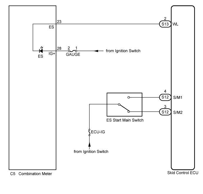
WIRING DIAGRAM
INSPECTION PROCEDURE
PROCEDURE
-
CHECK DTC
-
Check if ABS system DTC or ES start system DTC are output Click here.
Result Result Proceed to DTC is not output A DTC is output (for ABS system) B DTC is output (for ES start system) C
B 
REPAIR CIRCUITS INDICATED BY OUTPUT DTCS (FOR ABS SYSTEM) Click here
C
REPAIR CIRCUITS INDICATED BY OUTPUT DTCS (FOR ES START SYSTEM) Click here
A 
-
-
CHECK IF SKID CONTROL ECU CONNECTOR IS SECURELY CONNECTED
-
Check if the skid control ECU connector is securely connected.
OK The connector is securely connected.
NG
CONNECT CONNECTOR TO ECU CORRECTLY
OK
-
-
CHECK HARNESS AND CONNECTOR (SKID CONTROL ECU - COMBINATION METER)
-
Turn the ignition switch off.
-
Disconnect the skid control ECU connector and combination meter connector.
-
Measure the resistance according to the value(s) in the table below.
Standard Resistance Tester Connection Condition Specified Condition S13-2 (WL) - C5-23 (ES) Always Below 1 Ω S13-2 (WL) - Body ground Always 10 KΩ or higher
NG
REPAIR OR REPLACE HARNESS OR CONNECTOR
OK
-
-
INSPECT COMBINATION METER
-
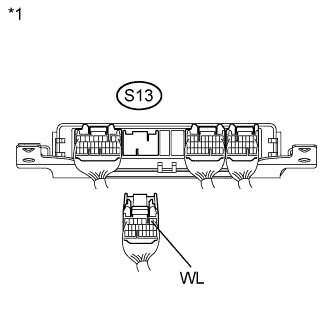
Text in Illustration *1 Rear view of wire harness connector
(to Skid Control ECU)
Reconnect the combination meter connector.
-
Connect the 2 batteries in series and apply 24 V to terminal S13-2 (WL) of the wire harness connector.
-
Check the combination meter.
OK The ES start indicator light comes on. Tech Tips
If troubleshooting has been carried out according to Problem Symptoms Table, refer back to the table and proceed to the next step Click here.
NG
REPLACE COMBINATION METER
OK 
REPLACE SKID CONTROL ECU
-