EASY AND SMOOTH START SYSTEM, Diagnostic DTC:P1143/44

| DTC Code | DTC Name |
|---|---|
| P1143/44 | Idle Volume High |
DESCRIPTION
| DTC No. | Detection Condition | Trouble Area |
|---|---|---|
| P1143/44 | Idle volume voltage is 4.59 V or more. |
|
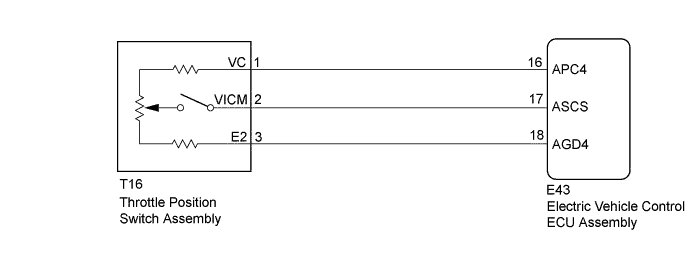
WIRING DIAGRAM
INSPECTION PROCEDURE
Note
-
After replacing the electric vehicle control ECU assembly, perform clutch pedal stroke sensor assembly release position calibration Click here.
-
DTCs stored in the electric vehicle control ECU assembly are not cleared even after the system returns to a normal condition, so clear the DTCs after performing troubleshooting Click here.
PROCEDURE
-
CHECK ELECTRIC VEHICLE CONTROL ECU ASSEMBLY (ASCS, APC4 TERMINAL)
-
Turn the ignition switch to ON.
-
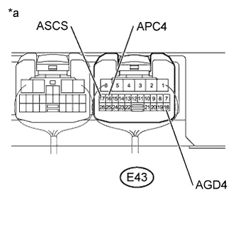
Text in Illustration *a Component with harness connected
(to Electric Vehicle Control ECU Assembly)
Measure the voltage according to the value(s) in the table below.
Standard Voltage Tester Connection Switch Condition Specified Condition E43-16 (APC4) - E43-18 (AGD4) Ignition switch ON 4.5 to 5.5 V E43-17 (ASCS) - E43-18 (AGD4) Ignition switch ON
Throttle position switch assembly off
0 V Ignition switch ON
Throttle position switch assembly ON to MAX
0.5 to 4.5 V
(Voltage changes continuously)
NG 
INSPECT THROTTLE POSITION SWITCH ASSEMBLY Click here
OK 
-
-
CLEAR DTC
-
Clear the DTCs Click here.
NEXT
-
-
CHECK FOR DTC
-
Check for DTCs Click here.
Result Result Proceed to DTC is not output A DTC is output B
B 
REPLACE ELECTRIC VEHICLE CONTROL ECU ASSEMBLY Click here
A 
USE SIMULATION METHOD TO CHECK Click here
-
-
INSPECT THROTTLE POSITION SWITCH ASSEMBLY
-
Turn the ignition switch off.
-
Remove the throttle position switch assembly.
-
Measure the resistance according to the value(s) in the table below.
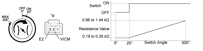
Text in Illustration *a Component without harness connected
(Throttle Position Switch Assembly)
- - Standard Resistance Tester Connection Switch Condition Specified Condition 2 (VICM) - 3 (E2) OFF 10 kΩ or higher ON(20°) 0.19 to 0.26 kΩ MAX(300°) 0.96 to 1.44 kΩ ON (20°) to MAX (300°) Changes continuously
NG
REPLACE THROTTLE POSITION SWITCH ASSEMBLY
OK
-
-
CHECK HARNESS AND CONNECTOR (ELECTRIC VEHICLE CONTROL ECU ASSEMBLY - THROTTLE POSITION SWITCH ASSEMBLY)
-
Turn the ignition switch off.
-
Disconnect the E43 electric vehicle control ECU assembly connector.
-
Disconnect the T16 throttle position switch assembly.
-
Measure the resistance according to the value(s) in the table below.
Standard Resistance Tester Connection Condition Specified Condition E43-16 (APC4) - T16-1 (VC) Always Below 1 Ω E43-17 (ASCS) - T16-2 (VICM) Always Below 1 Ω E43-18 (AGD4) - T16-3 (E2) Always Below 1 Ω E43-16 (APC4) or T16-1 (VC) - Body ground Always 10 kΩ or higher E43-17 (ASCS) or T16-2 (VICM) - Body ground Always 10 kΩ or higher E43-18 (AGD4) or T16-3 (E2) - Body ground Always 10 kΩ or higher
NG
REPAIR OR REPLACE HARNESS OR CONNECTOR
OK
REPLACE ELECTRIC VEHICLE CONTROL ECU ASSEMBLY Click here
-