EASY AND SMOOTH START SYSTEM, Diagnostic DTC:P0830/41

| DTC Code | DTC Name |
|---|---|
| P0830/41 | Clutch Pedal Switch "A" Circuit |
DESCRIPTION
| DTC No. | Detection Condition | Trouble Area |
|---|---|---|
| P0830/41 | After accelerating from 0 to 80 km/h, the clutch switch (exhaust retarder switch assembly) has not changed even once. |
|
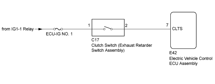
WIRING DIAGRAM
INSPECTION PROCEDURE
Note
-
After replacing the electric vehicle control ECU assembly, perform clutch pedal stroke sensor assembly release position calibration Click here.
-
Inspect the fuses for circuits related to this system before performing the following inspection procedure.
-
DTCs stored in the electric vehicle control ECU assembly are not cleared even after the system returns to a normal condition, so clear the DTCs after performing troubleshooting Click here.
Tech Tips
DTC P0830/41 is also output if the driver leaves their foot on the clutch pedal while driving the vehicle. Operate the clutch pedal and check the Data List item "Clutch Switch", and if there is no malfunction in the Data List and this DTC becomes a history DTC, then this DTC did not indicate a malfunction Click here.
PROCEDURE
-
CHECK CLUTCH SWITCH (EXHAUST RETARDER SWITCH ASSEMBLY) INSTALLATION
-
Check the installation condition of the clutch switch (exhaust retarder switch assembly) Click here.
OK Correctly installed.
NG 
INSTALL CLUTCH SWITCH (EXHAUST RETARDER SWITCH ASSEMBLY) CORRECTLY Click here
OK 
-
-
CHECK ELECTRIC VEHICLE CONTROL ECU ASSEMBLY (CLTS TERMINAL)
-
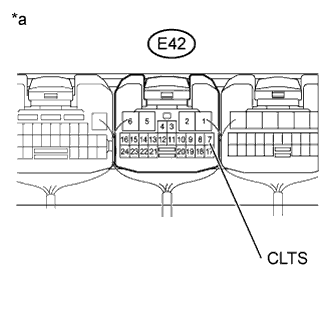
Text in Illustration *a Component with harness connected
(to Electric Vehicle Control ECU Assembly)
Turn the ignition switch to ON.
-
Measure the voltage according to the value(s) in the table below.
Standard Voltage Tester Connection Switch Condition Specified Condition E42-7 (CLTS) - Body ground Ignition switch ON
Clutch pedal depressed
Below 1 V Ignition switch ON
Clutch pedal released
20 V or higher
NG 
INSPECT CLUTCH SWITCH (EXHAUST RETARDER SWITCH ASSEMBLY) Click here
OK
-
-
CLEAR DTC
-
Clear the DTCs Click here.
NEXT
-
-
CHECK FOR DTC
-
Check for DTCs Click here.
Result Result Proceed to DTC is not output A DTC is output B
B
REPLACE ELECTRIC VEHICLE CONTROL ECU ASSEMBLY Click here
A 
USE SIMULATION METHOD TO CHECK Click here
-
-
INSPECT CLUTCH SWITCH (EXHAUST RETARDER SWITCH ASSEMBLY)
-
Turn the ignition switch off.
-
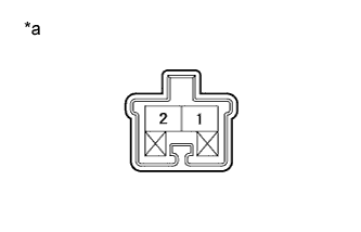
Text in Illustration *a Component without harness connected
(Clutch Switch (Exhaust Retarder Switch Assembly))
Remove the clutch switch (exhaust retarder switch assembly).
-
Measure the resistance according to the value(s) in the table below.
Standard Resistance Tester Connection Switch Condition Specified Condition 1 - 2 Switch pin free 10 kΩ or higher Switch pin pushed in Below 1 Ω
NG
REPLACE CLUTCH SWITCH (EXHAUST RETARDER SWITCH ASSEMBLY) Click here
OK
-
-
CHECK HARNESS AND CONNECTOR (ELECTRIC VEHICLE CONTROL ECU ASSEMBLY- CLUTCH SWITCH (EXHAUST RETARDER SWITCH ASSEMBLY))
-
Turn the ignition switch off.
-
Disconnect the E42 electric vehicle control ECU assembly connector.
-
Disconnect the C17 clutch switch (exhaust retarder switch assembly).
-
Measure the resistance according to the value(s) in the table below.
Standard Resistance Tester Connection Condition Specified Condition E42-7 (CLTS) - C17-2 Always Below 1 Ω E42-7 (CLTS) or C17-2 - Body ground Always 10 kΩ or higher
NG
REPAIR OR REPLACE HARNESS OR CONNECTOR
OK
-
-
CHECK HARNESS AND CONNECTOR (CLUTCH SWITCH (EXHAUST RETARDER SWITCH ASSEMBLY) POWER SOURCE CIRCUIT)
-
Turn the ignition switch off.
-
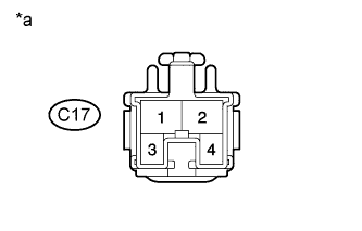
Text in Illustration *a Front view of wire harness connector
(Clutch Switch (Exhaust Retarder Switch Assembly))
Measure the voltage according to the value(s) in the table below.
Standard Voltage Tester Connection Switch Condition Specified Condition C17-1 - Body ground Ignition switch ON 20 V or higher Ignition switch off Below 1 V
NG
REPAIR OR REPLACE HARNESS OR CONNECTOR
OK
REPLACE ELECTRIC VEHICLE CONTROL ECU ASSEMBLY Click here
-