EASY AND SMOOTH START SYSTEM, Diagnostic DTC:P0833/15

| DTC Code | DTC Name |
|---|---|
| P0833/15 | Clutch Pedal Switch "B" Circuit |
TECHNICAL DESCRIPTION
| DTC No. | Detection Condition | Trouble Area |
|---|---|---|
| P0833/15 | At a vehicle speed of 10 km/h or more with the vehicle in gear, the power takeoff clutch switch assembly is ON for 60 seconds continuously. |
|
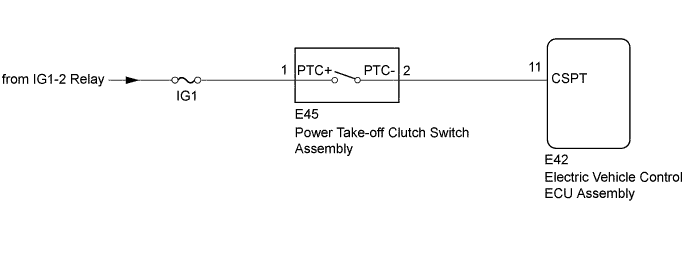
WIRING DIAGRAM
INSPECTION PROCEDURE
Note
-
After replacing the electric vehicle control ECU assembly, perform clutch pedal stroke sensor assembly release position calibration Click here.
-
Inspect the fuses for circuits related to this system before performing the following inspection procedure.
-
DTCs stored in the electric vehicle control ECU assembly are not cleared even after the system returns to a normal condition, so clear the DTCs after performing troubleshooting Click here.
PROCEDURE
-
CHECK ELECTRIC VEHICLE CONTROL ECU ASSEMBLY (CSPT TERMINAL)
-
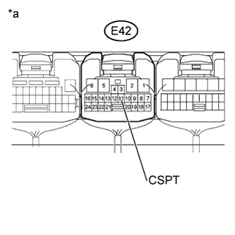
Text in Illustration *a Component with harness connected
(to Electric Vehicle Control ECU Assembly)
Turn the ignition switch to ON.
-
Measure the voltage according to the value(s) in the table below.
Standard Voltage Tester Connection Switch Condition Specified Condition E42-11 (CSPT) - Body ground Ignition switch ON
Clutch pedal released
Below 1 V Ignition switch ON
Clutch pedal fully depressed
20 V or higher
NG 
INSPECT POWER TAKE-OFF CLUTCH SWITCH ASSEMBLY Click here
OK 
-
-
CLEAR DTC
-
Clear the DTCs Click here.
NEXT
-
-
CHECK FOR DTC
-
Check for DTCs Click here.
Result Result Proceed to DTC is not output A DTC is output B
B 
REPLACE ELECTRIC VEHICLE CONTROL ECU ASSEMBLY Click here
A 
USE SIMULATION METHOD TO CHECK Click here
-
-
INSPECT POWER TAKE-OFF CLUTCH SWITCH ASSEMBLY
-
Turn the ignition switch off.
-
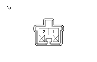
Text in Illustration *a Component without harness connected
(Power Take-off Clutch Switch Assembly)
Remove the power take-off clutch switch assembly.
-
Measure the resistance according to the value(s) in the table below.
Standard Resistance Tester Connection Switch Condition Specified Condition 1 - 2 Switch pin free 10 kΩ or higher Switch pin pushed in Below 1 Ω
NG
REPLACE POWER TAKE-OFF CLUTCH SWITCH ASSEMBLY Click here
OK
-
-
CHECK HARNESS AND CONNECTOR (ELECTRIC VEHICLE CONTROL ECU ASSEMBLY - POWER TAKE-OFF CLUTCH SWITCH ASSEMBLY)
-
Turn the ignition switch off.
-
Disconnect the E42 electric vehicle control ECU assembly connector.
-
Disconnect the E45 power take-off clutch switch assembly.
-
Measure the resistance according to the value(s) in the table below.
Standard Resistance Tester Connection Condition Specified Condition E42-11 (CSPT) - E45-2 (PTC-) Always Below 1 Ω E42-11 (CSPT) or E45-2 (PTC-) - Body ground Always 10 kΩ or higher
NG
REPAIR OR REPLACE HARNESS OR CONNECTOR
OK
-
-
CHECK HARNESS AND CONNECTOR (POWER TAKE-OFF CLUTCH SWITCH ASSEMBLY (POWER SOURCE CIRCUIT))
-
Turn the ignition switch off.
-
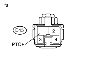
Text in Illustration *a Front view of wire harness connector
(Power Take-off Clutch Switch Assembly)
Measure the resistance according to the value(s) in the table below.
Standard Voltage Tester Connection Switch Condition Specified Condition E45-1 (PTC+) - Body ground Ignition switch ON 20 V or higher Ignition switch off Below 1 V
NG
REPAIR OR REPLACE HARNESS OR CONNECTOR
OK
REPLACE ELECTRIC VEHICLE CONTROL ECU ASSEMBLY Click here
-