EASY AND SMOOTH START SYSTEM, Diagnostic DTC:P081D/7

| DTC Code | DTC Name |
|---|---|
| P081D/7 | Neutral SW |
DESCRIPTION
| DTC No. | Detection Condition | Trouble Area |
|---|---|---|
| P081D/7 | After accelerating from 0 to 80 km/h, the neutral position switch has not changed even once. |
|
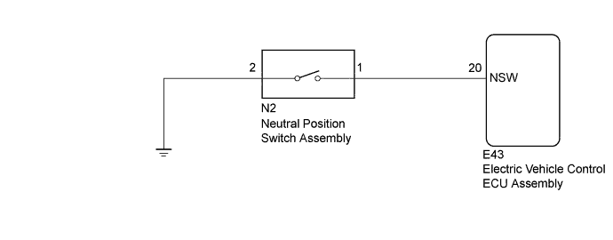
WIRING DIAGRAM
INSPECTION PROCEDURE
Note
-
DTCs stored in the electric vehicle control ECU assembly are not cleared even after the system returns to a normal condition, so clear the DTCs after performing troubleshooting Click here.
-
After performing inspection and repairs, if DTC P081D/7 is being output as a current DTC, turn the ignition switch to ON and move the shift lever back and forth several times between N and in-gear, so that the DTC becomes a history DTC. After changing to a history DTC, the DTC can be cleared using the intelligent tester Click here.
Tech Tips
DTC P081D/7 is judged to be normal when the electric vehicle control ECU detects that the neutral position switch changes normally.
PROCEDURE
-
CHECK HARNESS AND CONNECTOR (ELECTRIC VEHICLE CONTROL ECU ASSEMBLY - NEUTRAL POSITION SWITCH ASSEMBLY)
-
Turn the ignition switch off.
-
Disconnect the E43 electric vehicle control ECU assembly connector.
-
Disconnect the N2 neutral position switch assembly connector.
-
Measure the resistance according to the value(s) in the table below.
Standard Resistance Tester Connection Condition Specified Condition E43-20 (NSW) - N2-1 Always Below 1 Ω E43-20 (NSW) or N2-1 - Body ground Always 10 kΩ or higher -
Reconnect the E43 electric vehicle control ECU assembly connector.
-
Reconnect the N2 neutral position switch assembly connector.
NG 
REPAIR OR REPLACE HARNESS OR CONNECTOR
OK 
-
-
CHECK ELECTRIC VEHICLE CONTROL ECU ASSEMBLY (NSW TERMINAL)
-
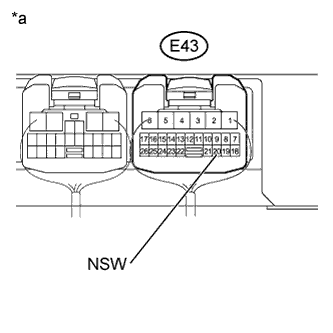
Text in Illustration *a Component with harness connected
(to Electric Vehicle Control ECU Assembly)
Turn the ignition switch to ON.
-
Measure the voltage according to the value(s) in the table below.
Standard Voltage Tester Connection Switch Condition Specified Condition E43-20 (NSW) - Body ground Ignition switch ON
Shift lever in N
20 V or higher
NG 
CHECK HARNESS AND CONNECTOR (NEUTRAL POSITION SWITCH ASSEMBLY - BODY GROUND) Click here
OK
-
-
CHECK ELECTRIC VEHICLE CONTROL ECU ASSEMBLY (NSW TERMINAL)
-
Text in Illustration *a Component with harness connected
(to Electric Vehicle Control ECU Assembly)
Turn the ignition switch to ON.
-
Measure the voltage according to the value(s) in the table below.
Standard Voltage Tester Connection Switch Condition Specified Condition E43-20 (NSW) - Body ground Ignition switch ON
Shift lever not in N
Below 1 V
NG
REPAIR OR REPLACE HARNESS OR CONNECTOR
OK
-
-
READ VALUE USING INTELLIGENT TESTER
-
Warm up the engine.
-
Turn the ignition switch off.
-
Replace the normal DLC3 cable (12 V specification) for the intelligent tester with the 24 V DLC3 cable.
Note
Be sure to use the 24 V DLC3 cable when connecting the intelligent tester to the DLC3. Using the normal DLC3 cable (12 V specification) will cause damage to the tester.
-
Connect the intelligent tester to the DLC3.
-
Turn the ignition switch to ON.
-
Turn the intelligent tester on.
-
Enter the following menus: Powertrain / Vehicle Control / Data List.
-
According to the display on the intelligent tester, read the Data List.
Vehicle Control Tester Display Measurement Item/Range Normal Condition Diagnostic Note Neutral Switch Shift lever neutral switch/
OFF / ON
OFF: Shift lever not in N
ON: Shift lever in N
- -
Read the value when the shift lever is in neutral and any other position.
OK ON is displayed when the shift lever is in neutral. OFF is displayed when the shift lever is in any other position.
NG
REPLACE ELECTRIC VEHICLE CONTROL ECU ASSEMBLY Click here
OK 
USE SIMULATION METHOD TO CHECK Click here
-
-
CHECK HARNESS AND CONNECTOR (NEUTRAL POSITION SWITCH ASSEMBLY - BODY GROUND)
-
Turn the ignition switch off.
-
Disconnect the N2 neutral position switch assembly connector.
-
Measure the resistance according to the value(s) in the table below.
Standard Resistance Tester Connection Condition Specified Condition N2-2 - Body ground Always Below 1 Ω
NG
REPAIR OR REPLACE HARNESS OR CONNECTOR
OK
REPLACE NEUTRAL POSITION SWITCH ASSEMBLY
-