EASY AND SMOOTH START SYSTEM, Diagnostic DTC:P0562/5, P0563/5

| DTC Code | DTC Name |
|---|---|
| P0562/5 | System Voltage Low |
| P0563/5 | System Voltage High |
DESCRIPTION
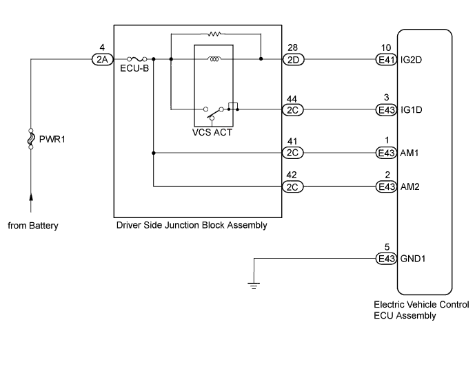
The electric vehicle control ECU assembly monitors for malfunctions in the battery voltage or power supply circuit, and prohibits ES system control system if a malfunction is detected.
| DTC No. | Detection Condition | Trouble Area |
|---|---|---|
| P0562/5 | Abnormally low power supply voltage detected (less than 16 V). |
|
| P0563/5 | Abnormally high power supply voltage detected (more than 32 V). |
WIRING DIAGRAM
INSPECTION PROCEDURE
Note
-
After replacing the electric vehicle control ECU assembly, perform clutch pedal stroke sensor assembly release position calibration Click here.
-
Inspect the fuses for circuits related to this system before performing the following inspection procedure.
-
DTCs stored in the electric vehicle control ECU assembly are not cleared even after the system returns to a normal condition, so clear the DTCs after performing troubleshooting Click here.
PROCEDURE
-
CHECK ELECTRIC VEHICLE CONTROL ECU ASSEMBLY (AM1, AM2 TERMINAL)
-
Turn the ignition switch to ON.
-
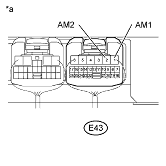
Text in Illustration *a Component with harness connected
(to Electric Vehicle Control ECU Assembly)
Measure the voltage according to the value(s) in the table below.
Standard Voltage Tester Connection Condition Specified Condition E43-1 (AM1) - Body ground Always 20 to 28 V E43-2 (AM2) - Body ground Always 20 to 28 V
NG 
CHECK HARNESS AND CONNECTOR (ELECTRIC VEHICLE CONTROL ECU ASSEMBLY - BATTERY) Click here
OK 
-
-
CHECK ELECTRIC VEHICLE CONTROL ECU ASSEMBLY (GND1 TERMINAL)
-
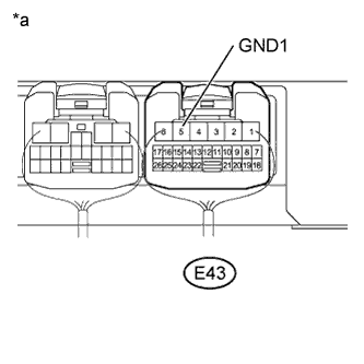
Text in Illustration *a Component with harness connected
(to Electric Vehicle Control ECU Assembly)
Turn the ignition switch to ON.
-
Measure the voltage according to the value(s) in the table below.
Standard Voltage Tester Connection Switch Condition Specified Condition E43-5 (GND1) - Body ground Ignition switch ON Below 1 V
NG 
REPAIR OR REPLACE HARNESS OR CONNECTOR
OK
-
-
PERFORM ACTIVE TEST USING INTELLIGENT TESTER
-
Warm up the engine.
-
Turn the ignition switch off.
-
Replace the normal DLC3 cable (12 V specification) for the intelligent tester with the 24 V DLC3 cable.
Note
Be sure to use the 24 V DLC3 cable when connecting the intelligent tester to the DLC3. Using the normal DLC3 cable (12 V specification) will cause damage to the tester.
-
Connect the intelligent tester to the DLC3.
-
Turn the ignition switch to ON.
-
Turn the intelligent tester on.
-
Enter the following menus: Powertrain / Vehicle Control / Active Test.
-
According to the display on the intelligent tester, perform the Active Test.
Vehicle Control Tester Display Test Part Control Range Diagnostic Note Actuator Relay VCS ACT relay Relay ON / OFF Test is possible when the following conditions are met:
-
Engine stopped
-
Shift lever in N
-
Ignition switch is ON
-
-
Check for operating sound of the VCS ACT relay when operating it with the intelligent tester.
OK Actuator relay operates correctly (relay operating sound can be heard).
NG
OK
-
-
CHECK DRIVER SIDE JUNCTION BLOCK ASSEMBLY
-
Turn the ignition switch off.
-
Disconnect the driver side junction block assembly connector.
-
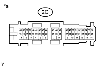
Text in Illustration *a Component without harness connected
(Driver Side Junction Block Assembly)
Measure the resistance according to the value(s) in the table below.
Standard Voltage Tester Connection Switch Condition Specified Condition 2C-44 - Body ground Ignition switch ON 20 to 28 V -
Reconnect the driver side junction block assembly connector.
NG
REPLACE DRIVER SIDE JUNCTION BLOCK ASSEMBLY Click here
OK
-
-
CHECK HARNESS AND CONNECTOR (DRIVER SIDE JUNCTION BLOCK ASSEMBLY - ELECTRIC VEHICLE CONTROL ECU ASSEMBLY)
-
Turn the ignition switch off.
-
Disconnect the electric vehicle control ECU assembly connector.
-
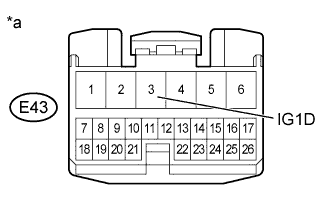
Text in Illustration *a Front view of wire harness connector
(Electric Vehicle Control ECU Assembly)
Measure the voltage according to the value(s) in the table below.
Standard Voltage Tester Connection Switch Condition Specified Condition E43-3 (IG1D) - Body ground Ignition switch ON 20 to 28 V -
Reconnect the electric vehicle control ECU assembly connector.
NG
REPAIR OR REPLACE HARNESS OR CONNECTOR
OK
-
-
CLEAR DTC
-
Clear the DTCs Click here.
NEXT
-
-
CHECK FOR DTC
-
Check for DTCs Click here.
Result Result Proceed to DTC is not output A DTC is output B
B
REPLACE ELECTRIC VEHICLE CONTROL ECU ASSEMBLY Click here
A 
USE SIMULATION METHOD TO CHECK Click here
-
-
CHECK HARNESS AND CONNECTOR (ELECTRIC VEHICLE CONTROL ECU ASSEMBLY - BATTERY)
Note
After turning the ignition switch off, waiting time may be required before disconnecting the cable from the negative (-) auxiliary battery terminal. Therefore, make sure to read the disconnecting the cable from the negative (-) auxiliary battery terminal notices before proceeding with work Click here.
-
Disconnect the cable from the negative (-) battery terminal.
-
Disconnect the cable from the positive (+) battery terminal.
-
Disconnect the E43 electric vehicle control ECU assembly connector.
-
Measure the resistance according to the value(s) in the table below.
Standard Resistance Tester Connection Condition Specified Condition E43-1 (AM1) - battery positive terminal Always Below 1 Ω E43-2 (AM2) - battery positive terminal Always Below 1 Ω E43-1 (AM1) or battery positive terminal - Body ground Always 10 kΩ or higher E43-2 (AM2) or battery positive terminal - Body ground Always 10 kΩ or higher
NG
REPAIR OR REPLACE HARNESS OR CONNECTOR
OK
GO TO CHARGING SYSTEM Click here
-
-
CHECK DRIVER SIDE JUNCTION BLOCK ASSEMBLY
-
Turn the ignition switch off.
-
Disconnect the driver side junction block assembly connector.
-
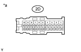
Text in Illustration *a Component without harness connected
(Driver Side Junction Block Assembly)
Measure the voltage according to the value(s) in the table below.
Standard Voltage Tester Connection Switch Condition Specified Condition 2D-28 - Body ground 15 seconds or more after ignition switch off 20 to 28 V -
Reconnect the driver side junction block assembly connector.
NG
REPLACE DRIVER SIDE JUNCTION BLOCK ASSEMBLY Click here
OK
-
-
CHECK HARNESS AND CONNECTOR (DRIVER SIDE JUNCTION BLOCK ASSEMBLY - ELECTRIC VEHICLE CONTROL ECU ASSEMBLY)
-
Turn the ignition switch off.
-
Disconnect the electric vehicle control ECU assembly connector.
-
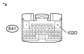
Text in Illustration *a Front view of wire harness connector
(Electric Vehicle Control ECU Assembly)
Measure the voltage according to the value(s) in the table below.
Standard Voltage Tester Connection Switch Condition Specified Condition E41-10 (1G2D) - Body ground 15 seconds or more after ignition switch off 20 to 28 V -
Reconnect the electric vehicle control ECU assembly connector.
NG
REPAIR OR REPLACE HARNESS OR CONNECTOR
OK
-
-
CHECK ELECTRIC VEHICLE CONTROL ECU ASSEMBLY
-
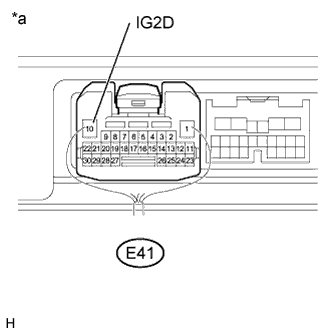
Text in Illustration *a Component with harness connected
(to Electric Vehicle Control ECU Assembly)
Measure the voltage according to the value(s) in the table below.
Standard Voltage Tester Connection Switch Condition Specified Condition E41-10 (IG2D) - Body ground Ignition switch ON Below 1 V
NG
REPLACE ELECTRIC VEHICLE CONTROL ECU ASSEMBLY Click here
OK
-
-
CLEAR DTC
-
Clear the DTCs Click here.
NEXT
-
-
CHECK FOR DTC
-
Check for DTCs Click here.
Result Result Proceed to DTC is not output A DTC is output B
B
REPLACE DRIVER SIDE JUNCTION BLOCK ASSEMBLY Click here
A
USE SIMULATION METHOD TO CHECK Click here
-