EASY AND SMOOTH START SYSTEM, Diagnostic DTC:C1386/28

| DTC Code | DTC Name |
|---|---|
| C1386/28 | ES Start Operation / Release Switch |
DESCRIPTION
| DTC No. | Detection Condition | Trouble Area |
|---|---|---|
| C1386/28 | The ON signal circuit and the off signal circuit of the ES start timing switch are both switched ON, or both off. |
|
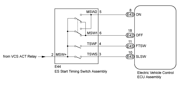
WIRING DIAGRAM
INSPECTION PROCEDURE
Note
-
After replacing the electric vehicle control ECU assembly, perform clutch pedal stroke sensor assembly release position calibration Click here.
-
DTCs stored in the electric vehicle control ECU assembly are not cleared even after the system returns to a normal condition, so clear the DTCs after performing troubleshooting Click here.
PROCEDURE
-
CHECK HARNESS AND CONNECTOR (ELECTRIC VEHICLE CONTROL ECU ASSEMBLY - ES START TIMING SWITCH ASSEMBLY)
-
Turn the ignition switch off.
-
Disconnect the E42 and E43 electric vehicle control ECU assembly connector.
-
Disconnect the E44 ES start timing switch assembly connector.
-
Measure the resistance according to the value(s) in the table below.
Standard Resistance Tester Connection Condition Specified Condition E43-8 (ON) - E44-5 (MSW2) Always Below 1 Ω E42-18 (OFF) - E44-6 (MSW1) Always Below 1 Ω E43-8 (ON) or E44-5 (MSW2) - Body ground Always 10 kΩ or higher E42-18 (OFF) or E44-6 (MSW1) - Body ground Always 10 kΩ or higher -
Reconnect the E42 and E43 electric vehicle control ECU assembly connector.
-
Reconnect the E44 ES start timing switch assembly connector.
NG 
REPAIR OR REPLACE HARNESS OR CONNECTOR
OK 
-
-
CHECK HARNESS AND CONNECTOR (EED TERMINAL)
-
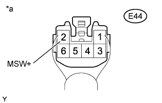
Text in Illustration *a Component with harness connected
(ES Start Timing Switch Assembly)
Measure the voltage according to the value(s) in the table below.
Standard Voltage Tester Connection Switch Condition Specified Condition E44-2 (MSW+) - Body ground Ignition switch ON 20 to 28 V
NG
REPAIR OR REPLACE HARNESS OR CONNECTOR
OK
-
-
CHECK ES START TIMING SWITCH ASSEMBLY
-
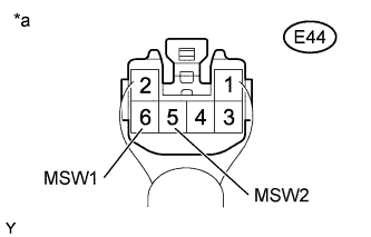
Text in Illustration *a Component with harness connected
(ES Start Timing Switch Assembly)
Measure the voltage according to the value(s) in the table below.
Standard Voltage Tester Connection Switch Condition Specified Condition E44-5 (MSW2) - Body ground Ignition switch ON
ES start timing switch assembly ON
20 to 28 V Ignition switch ON
ES start timing switch assembly off
Below 1 V E44-6 (MSW1) - Body ground Ignition switch ON
ES start timing switch assembly ON
Below 1 V Ignition switch ON
ES start timing switch assembly off
20 to 28 V
NG
REPLACE ES START TIMING SWITCH ASSEMBLY Click here
OK
-
-
READ VALUE USING INTELLIGENT TESTER
-
Warm up the engine.
-
Turn the ignition switch off.
-
Replace the normal DLC3 cable (12 V specification) for the intelligent tester with the 24 V DLC3 cable.
Note
Be sure to use the 24 V DLC3 cable when connecting the intelligent tester to the DLC3. Using the normal DLC3 cable (12 V specification) will cause damage to the tester.
-
Connect the intelligent tester to the DLC3.
-
Turn the ignition switch to ON.
-
Turn the intelligent tester on.
-
Enter the following menus: Powertrain / Vehicle Control / Data List.
-
According to the display on the intelligent tester, read the Data List.
Vehicle Control Tester Display Measurement Item/Range Normal Condition Diagnostic Note ES Start Main Switch (ON) ES start timing switch (ON) /
OFF / ON
OFF: ES start timing switch off
ON: ES start timing switch ON
- ES Start Main Switch (OFF) ES start timing switch (OFF) /
OFF / ON
OFF: ES start timing switch ON
ON: ES start timing switch off
- -
Using the intelligent tester, check that the switch condition displayed on the intelligent tester changes according to ES start timing switch assembly operation.
OK The intelligent tester display changes in response to operation of the ES start timing switch assembly.
NG
REPLACE ELECTRIC VEHICLE CONTROL ECU ASSEMBLY Click here
OK
-
-
CLEAR DTC
-
Clear the DTCs Click here.
NEXT
-
-
CHECK FOR DTC
-
Check for DTCs Click here.
Result Result Proceed to DTC is not output A DTC is output B
B
REPLACE ELECTRIC VEHICLE CONTROL ECU ASSEMBLY Click here
A 
USE SIMULATION METHOD TO CHECK Click here
-