EASY AND SMOOTH START SYSTEM, Diagnostic DTC:C1384/113

| DTC Code | DTC Name |
|---|---|
| C1384/113 | Neutral Switch |
DESCRIPTION
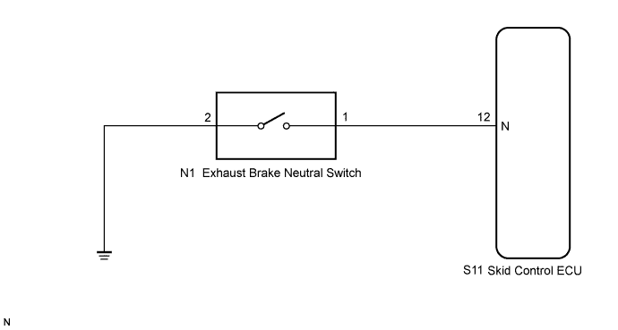
The skid control ECU receives a neutral gear position signal from the exhaust brake neutral switch assembly of the transmission.
| DTC Code | DTC Detection Condition | Trouble Area |
|---|---|---|
| C1384/113 | While accelerating from 5 km/h (3 mph) to 50 km/h (31 mph), neutral switch input does not change for 5 times consecutively. |
|
WIRING DIAGRAM
INSPECTION PROCEDURE
PROCEDURE
-
INSPECT EXHAUST BRAKE NEUTRAL SWITCH
-
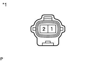
Text in Illustration *1 Component without harness connected
(Exhaust Brake Neutral Switch)
Disconnect the exhaust brake neutral switch connector.
-
Measure the resistance according to the value(s) in the table below.
Standard Resistance Tester Connection Condition Specified Condition 1 - 2 Shift lever in N 10 kΩ or higher Shift lever not in N Below 1 Ω
NG 
REPLACE EXHAUST BRAKE NEUTRAL SWITCH
OK 
-
-
INSPECT SKID CONTROL ECU (N CIRCUIT)
-
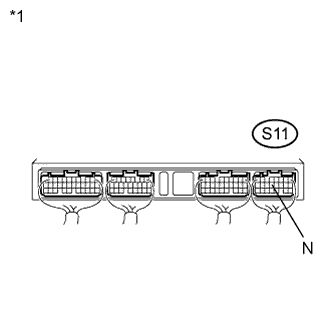
Text in Illustration *1 Component with harness connected
(Skid Control ECU)
Install the exhaust brake neutral switch connector.
-
Turn the ignition switch to ON.
-
Measure the voltage according to the value(s) in the table below.
Standard Voltage Tester Connection Condition Specified Condition S11-12 (N) - Body ground Shift lever in N 20 to 32 V Shift lever not in N Below 3 V
NG 
CHECK HARNESS AND CONNECTOR (EXHAUST BRAKE NEUTRAL SWITCH - SKID CONTROL ECU) Click here
OK
-
-
RECONFIRM DTC
-
Clear the DTCs Click here.
-
Perform a road test.
-
Check if the same DTC is recorded Click here.
Result Result Proceed to DTC (C1384/113) is not output A DTC (C1384/113) is output B Tech Tips
If troubleshooting has been carried out according to Problem Symptoms Table, refer back to the table and proceed to the next step Click here.
B
REPLACE SKID CONTROL ECU
A 
CHECK FOR INTERMITTENT PROBLEMS Click here
-
-
CHECK HARNESS AND CONNECTOR (EXHAUST BRAKE NEUTRAL SWITCH - SKID CONTROL ECU)
-
Turn the ignition switch off.
-
Disconnect the skid control ECU connector and exhaust brake neutral switch connector.
-
Measure the resistance according to the value(s) in the table below.
Standard Resistance Tester Connection Condition Specified Condition S11-12 (N) - N1-1 Always Below 1 Ω S11-12 (N) - Body ground Always 10 kΩ or higher N1-2 - Body ground Always Below 1 Ω
NG
REPAIR OR REPLACE HARNESS OR CONNECTOR
OK
REPLACE SKID CONTROL ECU
-