EASY AND SMOOTH START SYSTEM, Diagnostic DTC:C1383/111

| DTC Code | DTC Name |
|---|---|
| C1383/111 | Vehicle Speed Sensor |
DESCRIPTION
The skid control ECU receives vehicle speed signals from the speed sensors via the speedometer circuit.
| DTC Code | DTC Detection Condition | Trouble Area |
|---|---|---|
| C1383/111 | With the engine running, PKB1 terminal not connected, battery voltage normal and the vehicle driven at 20 km/h (12 mph) or more, vehicle speed signals are not received for 3 seconds or more. |
|
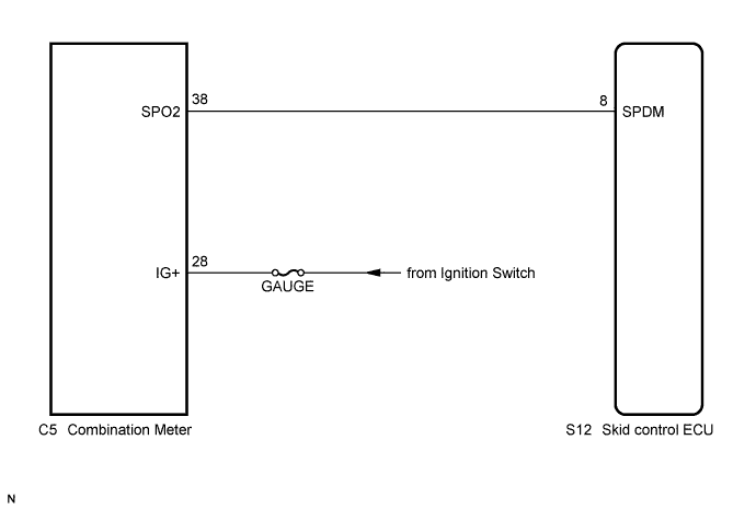
WIRING DIAGRAM
INSPECTION PROCEDURE
PROCEDURE
-
CHECK SPEEDOMETER
-
Check that there is no abnormal vehicle speed drop or fluctuations on the speedometer in the combination meter Click here.
OK Abnormality is not found in the speedometer display.
NG 
GO TO METER / GAUGE SYSTEM
OK 
-
-
CHECK HARNESS AND CONNECTOR (COMBINATION METER - SKID CONTROL ECU)
-
Turn the ignition switch off.
-
Disconnect the skid control ECU connector and combination meter connector.
-
Measure the resistance according to the value(s) in the table below.
Standard Resistance Tester Connection Condition Specified Condition S12-8 (SPDM) - C5-38 (SPO2) Always Below 1 Ω S12-8 (SPDM) - Body ground Always 10 kΩ or higher
NG
REPAIR OR REPLACE HARNESS OR CONNECTOR
OK
-
-
INSPECT SKID CONTROL ECU (SPDM CIRCUIT)
-
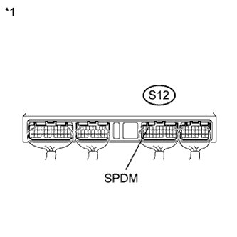
Text in Illustration *1 Component with harness connected
(Skid Control ECU)
Reconnect the skid control ECU connector and combination meter connector.
-
Turn the ignition switch to ON.
-
Measure the voltage according to the value(s) in the table below.
Standard Voltage Tester Connection Condition Specified Condition S12-8 (SPDM) - Body ground Ignition switch ON Below 2 V ←→ 10 V or more Result Result Proceed to Below 2 V ←→ 10 V or more A Below 2 V B 10 V or higher C
B
REPLACE SKID CONTROL ECU
C
REPLACE COMBINATION METER
A
-
-
RECONFIRM DTC
-
Clear the DTCs Click here.
-
Perform a road test.
-
Check if the same DTC is recorded Click here.
Result Result Proceed to DTC (C1383/111) is not output A DTC (C1383/111) is output B Tech Tips
If troubleshooting has been carried out according to Problem Symptoms Table, refer back to the table and proceed to the next step Click here.
B
REPLACE SKID CONTROL ECU
A 
CHECK FOR INTERMITTENT PROBLEMS Click here
-