EASY AND SMOOTH START SYSTEM, Diagnostic DTC:C1382/21

| DTC Code | DTC Name |
|---|---|
| C1382/21 | Clutch Stroke Sensor |
DESCRIPTION
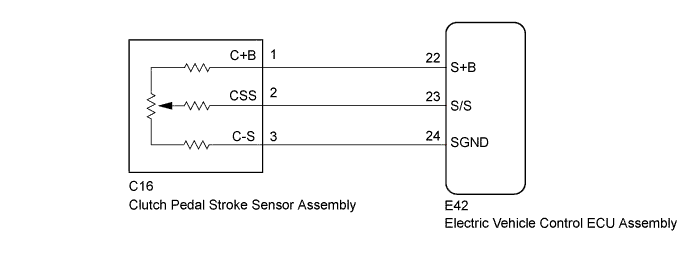
The clutch pedal stroke sensor assembly is installed to the upper part of the clutch pedal. It detects the amount that the clutch pedal is being depressed, and outputs a signal to the electric vehicle control ECU assembly.
The electric vehicle control ECU assembly memorizes the clutch release learning value.
| DTC No. | Detection Condition | Trouble Area |
|---|---|---|
| C1382/21 | When accelerating from 0 to 40 km/h, there is almost no change in the clutch pedal stroke sensor signal, and this occurs 5 times consecutively. |
|
WIRING DIAGRAM
INSPECTION PROCEDURE
Note
-
After replacing the electric vehicle control ECU assembly, perform clutch pedal stroke sensor assembly release position calibration Click here.
-
After replacing the clutch pedal stroke sensor assembly, perform clutch pedal stroke sensor zero point calibration and release position calibration Click here.
-
DTCs stored in the electric vehicle control ECU assembly are not cleared even after the system returns to a normal condition, so clear the DTCs after performing troubleshooting Click here.
PROCEDURE
-
CHECK HARNESS AND CONNECTOR (ELECTRIC VEHICLE CONTROL ECU ASSEMBLY - CLUTCH PEDAL STROKE SENSOR ASSEMBLY)
-
Turn the ignition switch off.
-
Disconnect the E42 electric vehicle control ECU assembly connector.
-
Disconnect the C16 clutch pedal stroke sensor assembly connector.
-
Measure the resistance according to the value(s) in the table below.
Standard Resistance Tester Connection Condition Specified Condition E42-22 (S+B) - C16-1 (C+B) Always Below 1 Ω E42-23 (S/S) - C16-2 (CSS) Always Below 1 Ω E42-24 (SGND) - C16-3 (C-S) Always Below 1 Ω E42-22 (S+B) or C16-1 (C+B) - Body ground Always 10 kΩ or higher E42-23 (S/S) or C16-2 (CSS) - Body ground Always 10 kΩ or higher E42-24 (SGND) or C16-3 (C-S) - Body ground Always 10 kΩ or higher -
Reconnect the E42 electric vehicle control ECU assembly connector.
-
Reconnect the C16 clutch pedal stroke sensor assembly connector.
NG 
REPAIR OR REPLACE HARNESS OR CONNECTOR
OK 
-
-
CHECK ELECTRIC VEHICLE CONTROL ECU ASSEMBLY (STB, SGND TERMINAL)
-
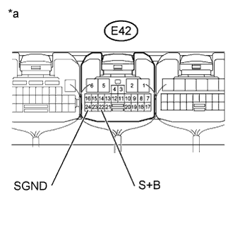
Text in Illustration *a Component with harness connected
(to Electric Vehicle Control ECU Assembly)
Measure the voltage according to the value(s) in the table below.
Standard Voltage Tester Connection Switch Condition Specified Condition E42-22 (S+B) - Body ground Ignition switch ON 4.75 to 5.25 V E42-24 (SGND) - Body ground Ignition switch ON Below 1 V
NG
REPLACE ELECTRIC VEHICLE CONTROL ECU ASSEMBLY Click here
OK
-
-
CHECK CLUTCH PEDAL STROKE SENSOR ASSEMBLY
-
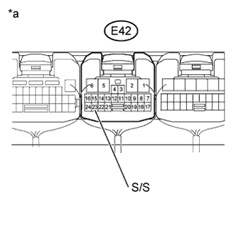
Text in Illustration *a Component with harness connected
(to Electric Vehicle Control ECU Assembly)
Measure the voltage according to the value(s) in the table below.
Standard Voltage Tester Connection Switch Condition Specified Condition E42-23 (S/S) - Body ground Ignition switch ON
Changes in proportion with the clutch pedal movement
0.5 to 4.5 V OK The voltage varies in response to the clutch pedal stroke amount.
NG
REPLACE CLUTCH PEDAL STROKE SENSOR ASSEMBLY Click here
OK
-
-
READ VALUE USING INTELLIGENT TESTER
-
Warm up the engine.
-
Turn the ignition switch off.
-
Replace the normal DLC3 cable (12 V specification) for the intelligent tester with the 24 V DLC3 cable.
Note
Be sure to use the 24 V DLC3 cable when connecting the intelligent tester to the DLC3. Using the normal DLC3 cable (12 V specification) will cause damage to the tester.
-
Connect the intelligent tester to the DLC3.
-
Turn the ignition switch to ON.
-
Turn the intelligent tester on.
-
Enter the following menus: Powertrain / Vehicle Control / Data List.
-
According to the display on the intelligent tester, read the Data List.
Vehicle Control Tester Display Measurement Item/Range Normal Condition Diagnostic Note Clutch Sensor Raw Signal Voltage of clutch stroke sensor /
Min.: 0.00 V, Max.: 6.00 V
Approximately 0.55 V: Clutch pedal released
Approximately 4.35 V: Clutch pedal fully depressed
- OK The voltage varies in response to the clutch pedal stroke amount.
NG
REPLACE ELECTRIC VEHICLE CONTROL ECU ASSEMBLY Click here
OK
-
-
CLEAR DTC
-
Clear the DTCs Click here.
NEXT
-
-
CHECK FOR DTC
-
Check for DTCs Click here.
Result Result Proceed to DTC is not output A DTC is output B
B
REPLACE ELECTRIC VEHICLE CONTROL ECU ASSEMBLY Click here
A 
USE SIMULATION METHOD TO CHECK Click here
-