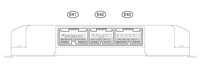
EASY AND SMOOTH START SYSTEM TERMINALS OF ECU

-
CHECK ELECTRIC VEHICLE CONTROL ECU ASSEMBLY
-
Disconnect the E43 electric vehicle control ECU assembly connector.
-
Measure the voltage and resistance according to the value(s) in the table below.
Tech Tips
Measure the values on the wire harness side with the connector disconnected.
Terminal No. (Symbols) Wiring Color Condition Specified Condition E43-1 (AM1) - Body ground B Always 16 V or higher E43-2 (AM2) - Body ground B Always 16 V or higher E43-13 (ACC) - Body ground G Ignition switch off Below 1 V Ignition switch ON 20 to 28 V E43-5 (GND1) - Body ground W-B Always Below 1Ω -
Reconnect the L36 electric vehicle control ECU assembly connector.
-
Measure the voltage and resistance according to the value(s) in the table below.
Terminal No. (Symbol) Wiring Color Terminal Description Condition Specified Condition E43-1 (AM1) - E43-5 (GND1) B - W-B AM1 power supply Always 20 to 28 V E43-2 (AM2) - E43-5 (GND1) B - W-B AM2 power supply Always 20 to 28 V E43-3 (IG1D) - E43-5 (GND1) LG - W-B Actuator power supply 15 seconds or more after ignition switch off Below 1 V Ignition switch ON 20 to 28 V E43-5 (GND1) - Body ground W-B Ground Always Below 1 Ω E43-7 (STSW) - E43-5 (GND1) L - W-B Starter signal input Ignition switch ON (starter motor not operating) Below 1 V Cranking (starter motor operating) 20 to 28 V E43-8 (ON) - E43-5 (GND1) B - W-B ES start timing switch ON input Ignition switch ON
ES start timing switch assembly ON
20 to 28 V Ignition switch ON
ES start timing switch assembly off
Below 1 V E43-9 (STP) - E43-5 (GND1) L - W-B Stop light switch input Stop light switch assembly ON (brake pedal depressed ) Below 1 V Stop light switch assembly off (brake pedal released) 20 V or higher E43-10 (SLSW) - E43-5 (GND1) G - W-B ES start timing switch SLOW input Ignition switch ON
ES start timing switch assembly pressed to SLOW side
20 to 28 V Ignition switch ON
ES start timing switch assembly SLOW side released
Below 1 V E43-11 (FTSW) - E43-5 (GND1) R - W-B ES start timing switch FAST input Ignition switch ON
ES start timing switch assembly pressed to FAST side
20 to 28 V Ignition switch ON
ES start timing switch assembly FAST side released
Below 1 V E43-13 (ACC) - E43-5 (GND1) G - W-B Ignition switch power supply Ignition switch off Below 1 V Ignition switch ON 20 to 28 V E43-16 (APC4) - E43-18 (AGD4) L - Y Throttle position switch power source Ignition switch ON 4.5 to 5.5 V E43-17 (ASCS) - E43-18 (AGD4) V - Y Throttle position switch input Ignition switch ON
Throttle position switch assembly off
0 V Ignition switch ON
Throttle position switch assembly ON to MAX
0.5 to 4.5 V
(Voltage changes continuously)
E43-18 (AGD4) - E43-5 (GND1) Y - W-B Throttle position switch ground Ignition switch ON Below 1 V E43-20 (NSW) - E43-5 (GND1) R - W-B Neutral switch input Ignition switch ON
Shift lever in N
20 to 28 V Ignition switch ON
Shift lever not in N
Below 1 V E43-21 (TC) - E43-5 (GND1) R - W-B TC terminal Ignition switch ON
Terminal TC connected
Below 1 V Ignition switch ON
Terminal TC not connected
20 to 28 V E43-22 (PKB) - E43-5 (GND1) R - W-B Parking brake switch input Ignition switch ON
Parking brake switch assembly ON (parking brake applied)
Below 1 V Ignition switch ON
Parking brake switch assembly off (parking brake released)
20 V or higher E43-23 (PCTY) - E43-5 (GND1) V - W-B Front RH courtesy switch input Ignition switch ON
Front RH door is open
Below 1 V Ignition switch ON
Front RH door closed
20 to 28 V E43-24 (DCTY) - E43-5 (GND1) P - W-B Front LH courtesy switch input Ignition switch ON
Front LH door open
Below 1 V Ignition switch ON
Front LH door closed
20 to 28 V E42-3 (PIND) - E43-5 (GND1) R - W-B ES start indicator light output Ignition switch ON
ES start indicator light ON → off
Below 1 V → 20 to 28 V E42-7 (CLTS) - E43-5 (GND1) L - W-B Clutch switch (exhaust retarder switch assembly) input Ignition switch ON
Clutch pedal depressed
Below 1 V Ignition switch ON
Clutch pedal released
20 V or higher E42-9 (SIND) - E43-5 (GND1) G - W-B Master warning light output Ignition switch ON
Master warning light ON → off
Below 1 V → 20 to 28 V E42-11 (CSPT) - E43-5 (GND1) L - W-B Power take-off clutch switch input Ignition switch ON
Clutch pedal released
Below 1 V Ignition switch ON
Clutch pedal fully depressed
20 V or higher E42-18 (OFF) - E43-5 (GND1) W - W-B ES start timing switch OFF input Ignition switch ON
ES start timing switch assembly off
20 to 28 V Ignition switch ON
ES start timing switch assembly ON
Below 1 V E42-22 (S+B) - E43-5 (GND1) W - W-B Clutch pedal stroke sensor power source Ignition switch ON 4.75 to 5.25 V E42-23 (S/S) - E43-5 (GND1) B - W-B Clutch pedal stroke sensor input Ignition switch ON
Changes in proportion with the pedal movement
0.5 to 4.5 V E42-24 (SGND) - E43-5 (GND1) P - W-B Clutch pedal stroke sensor ground Always Below 1 V E41-10 (IG2D) - E43-5 (GND1) B - W-B VCS ACT relay drive signal 15 seconds or more after ignition switch off 20 to 28 V Ignition switch ON Below 1 V E41-16 (CSW1) - E43-5 (GND1) G - W-B Exhaust brake main switch (windshield wiper switch assembly) input Ignition switch ON
Exhaust brake main switch (windshield wiper switch assembly) off
Below 1 V Ignition switch ON
Exhaust brake main switch (windshield wiper switch assembly) ON
20 to 28 V E41-17 (SPD) - E43-5 (GND1) L - W-B Vehicle speed signal input Vehicle being driven Pulse generation
(see waveform 1)
E41-30 (SIL) - E43-5 (GND1) W - W-B Diagnosis tester communication line Ignition switch ON
Communication not performed with tester
20 to 28 V -
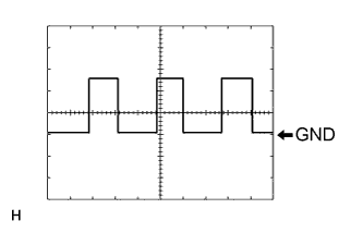
Using an oscilloscope, check waveform 1.
Item Contents Terminal No. (Symbol) E41-17 (SPD) - E43-5 (GND1) Tool Setting 5 V/DIV., 20 ms/DIV. Vehicle Condition Vehicle being driven at approximately 20 km/h (12 mph) Tech Tips
The wavelength becomes shorter as the vehicle speed increases.
-