EASY AND SMOOTH START SYSTEM TERMINALS OF ECU

-
CHECK BATTERY VOLTAGE
-
Check the battery voltage.
-
-
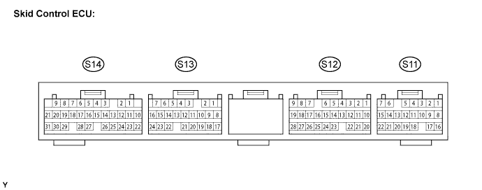
INSPECT SKID CONTROL ECU
-
Measure the voltage and resistance between each terminal and the body ground.
Note
-
Be sure to use the 24 V DLC3 cable when connecting the intelligent tester to the DLC3. Using the normal DLC3 cable (12 V specification) will cause damage to the tester.
-
Inspection should be performed from the back of the connector with the connector connected to the skid control ECU.
Tech Tips
Inspect the ECU from the wire harness side while the connector is connected.
Terminal No. (Symbols) Wiring Color Terminal Description Condition Specified Condition S11-12 (N) - Body ground B-O - Body ground Neutral switch input Ignition switch ON with shift lever in N 20 to 32 V Ignition switch ON with shift lever not in N Below 3 V S11-14 (GND4) - Body ground W-B - Body ground Skid control ECU ground 4 Always Below 1 Ω S11-15 (GND3) - Body ground W-B - Body ground Skid control ECU ground 3 Always Below 1 Ω S12-2 (DOOR) - Body ground L-O - Body ground Courtesy switch input Driver door closed 10 V or higher Driver door open Below 2 V S12-3 (S/M2) - Body ground L-R - Body ground ES start main switch OFF input Ignition switch ON, ES start main switch OFF → ON 20 to 32 V → 16 to 32 V S12-4 (S/M1) - Body ground R-W - Body ground ES start main switch ON input Ignition switch ON, ES start main switch ON → OFF 16 to 32 V → 20 to 32 V S12-5 (FAST) - Body ground G-W - Body ground ES start timing switch FAST input Ignition switch ON, ES start main switch ON → OFF 16 to 32 V → 20 to 32 V S12-6 (SLOW) - Body ground P-L - Body ground ES start timing switch SLOW input Ignition switch ON, ES start main switch ON → OFF 16 to 32 V → 20 to 32 V S12-7 (TACH) - Body ground P - Body ground Engine speed input Engine idling Below 2 V ←→ 10 V or more S12-8 (SPDM) - Body ground B - Body ground Vehicle speed signal input Vehicle being driven Below 2 V ←→ 10 V or more S13-1 (STP) - Body ground V - Body ground Stop light switch input Stop light switch ON → OFF (Brake pedal depressed → released) 16 to 32 V → Below 3 V S13-2 (WL) - Body ground LG-R - Body ground ES start indicator light output Ignition switch OFF → ON 7 to 18 V for approx. 3 seconds → Below 3 V S13-3 (BAT) - Body ground B-R - Body ground Battery Always 20 to 32 V S13-5 (BZ) - Body ground L-Y - Body ground ES start buzzer output Ignition switch ON, ES start buzzer operating Below 2 V S13-7 (IG1) - Body ground B-R - Body ground IG1 power supply Ignition switch ON 20 to 32 V S13-11 (PKB) - Body ground P-G - Body ground Parking brake switch 2 input Ignition switch ON, parking brake switch ON → OFF Below 2 V → 20 to 32 V S13-19 (TC) - Body ground R-B - Body ground Diagnosis activation input Ignition switch ON, terminals TC and CG of DLC3 connected → disconnected Below 3 V → 20 to 32 V S13-21 (PKB1) - Body ground B-L - Body ground Parking brake switch 1 input Ignition switch ON, parking brake switch ON → OFF Below 3 V → 10 to 32 V S14-2 (GND1) - Body ground W-B - Body ground Skid control ECU ground 1 Always Below 1 Ω S14-3 (GND2) - Body ground W-B - Body ground Skid control ECU ground 2 Always Below 1 Ω S14-4 (CL+) - Body ground L - Body ground Clutch pedal stroke sensor power source Ignition switch ON 3 to 5 V S14-15 (CLS) - Body ground L-R - Body ground Clutch pedal stroke sensor input Ignition switch ON, clutch pedal released → depressed Below 1 V → 26 V or higher S14-16 (CL-) - Body ground W-L - Body ground Clutch pedal stroke sensor ground Always Below 1 Ω -
-