ANTI-LOCK BRAKE SYSTEM Brake Warning Light Remains ON
DESCRIPTION
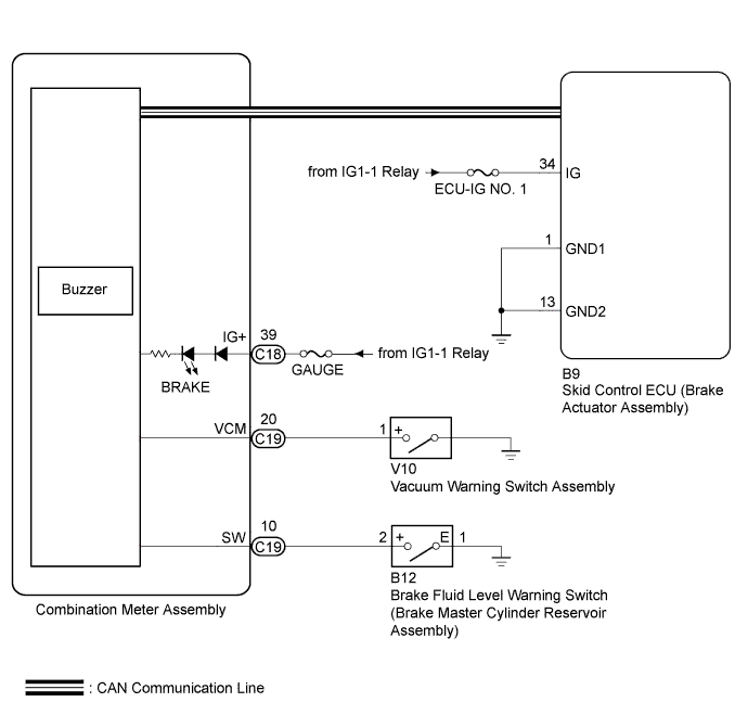
The skid control ECU (brake actuator assembly) is connected to the combination meter via CAN communication.
If any of the following is detected, the brake warning light remains on:
-
The skid control ECU (brake actuator assembly) connector is disconnected from the skid control ECU (brake actuator assembly).
-
The brake fluid level is insufficient.
-
The vacuum pressure is insufficient.
-
EBD operation is not possible.
WIRING DIAGRAM
INSPECTION PROCEDURE
Note
Inspect the fuses for circuits related to this system before performing the following inspection procedure.
PROCEDURE
-
PREPARE FOR INSPECTION
-
Check that both of the following conditions are satisfied.
-
The brake fluid level in the brake master cylinder reservoir is correct.
-
The parking brake is released.
Tech Tips
When the ABS warning light remains illuminated, repair the malfunction in the ABS system first.
-
NEXT 
-
-
CHECK CAN COMMUNICATION SYSTEM
-
Check if CAN communication system DTCs are output Click here.
Result Result Proceed to DTC is not output A DTC is output B
B 
GO TO CAN COMMUNICATION SYSTEM Click here
A
-
-
CHECK BRAKE ACTUATOR ASSEMBLY CONNECTOR IS SECURELY CONNECTED
-
Check if the skid control ECU (brake actuator assembly) connector is securely connected.
OK The connector is securely connected.
NG
CONNECT CONNECTOR TO ECU CORRECTLY
OK
-
-
CHECK VACUUM HOSE
-
Turn the ignition switch off.
-
Check the vacuum hose.
OK No cracks or damage on the vacuum hoses.
NG
REPLACE VACUUM HOSE
OK
-
-
INSPECT BRAKE FLUID LEVEL WARNING SWITCH (BRAKE MASTER CYLINDER RESERVOIR ASSEMBLY)
-
Turn the ignition switch off.
-
Remove the reservoir filler cap and strainer.
-
Disconnect the brake fluid level warning switch (brake master cylinder reservoir assembly) connector.
-
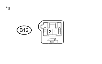
Text in Illustration *a Component without harness connected
(Brake Fluid Level Warning Switch (Brake Master Cylinder Reservoir Assembly)
Measure the resistance according to the value(s) in the table below.
Tech Tips
A float is located inside the reservoir. Its position can be changed by increasing or decreasing the level of brake fluid.
Standard Resistance Tester Connection Switch Condition Specified Condition 1 - 2 Switch OFF (Float up) 10 kΩ or higher 1 - 2 Switch ON (Float down) Below 1 Ω Tech Tips
If there is no problem after finishing the above check, adjust the brake fluid level to the MAX level.
-
Reinstall the reservoir filler cap and strainer.
NG
REPLACE BRAKE FLUID LEVEL WARNING SWITCH (BRAKE MASTER CYLINDER RESERVOIR ASSEMBLY)
OK
-
-
CHECK HARNESS AND CONNECTOR (COMBINATION METER ASSEMBLY - BRAKE FLUID LEVEL WARNING SWITCH (BRAKE MASTER CYLINDER RESERVOIR)
-
Disconnect the C19 combination meter assembly connector.
-
Measure the resistance according to the value(s) in the table below.
Standard Resistance Tester Connection Condition Specified Condition C19-10 (SW) - B12-2 Always Below 1 Ω B12-1 - Body ground Always Below 1 Ω C19-10 (SW) or B12-1 - Body ground Always 10 kΩ or higher -
Reconnect the C19 combination meter assembly connector.
-
Reconnect the B12 brake fluid level warning switch (brake master cylinder reservoir assembly).
NG
REPAIR OR REPLACE HARNESS OR CONNECTOR
OK
-
-
CHECK HARNESS AND CONNECTOR (POWER SOURCE TERMINAL)
-
Disconnect the vacuum warning switch assembly connector.
-
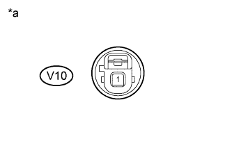
Text in Illustration *a Front view of wire harness connector
(to Vacuum Warning Switch Assembly)
Measure the voltage according to the value(s) in the table below.
Standard Voltage Tester Connection Switch Condition Specified Condition V10-1 - Body ground Ignition switch ON
Parking brake switch off
20 to 28 V -
Reconnect the vacuum warning switch assembly connector.
NG
REPAIR OR REPLACE HARNESS OR CONNECTOR (POWER SOURCE CIRCUIT)
OK
-
-
CHECK HARNESS AND CONNECTOR (IG TERMINAL)
-
Turn the ignition switch off.
-
Disconnect the skid control ECU (brake actuator assembly) connector.
-
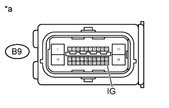
Text in Illustration *a Front view of wire harness connector
(to Skid Control ECU (Brake Actuator Assembly))
Measure the voltage according to the value(s) in the table below.
Standard Voltage Tester Connection Switch Condition Specified Condition B9-34 (IG) - Body ground Ignition switch ON 20 to 28 V
NG
REPAIR OR REPLACE HARNESS OR CONNECTOR (IG CIRCUIT)
OK
-
-
CHECK HARNESS AND CONNECTOR (GND1, GND2 TERMINAL)
-
Turn the ignition switch off.
-
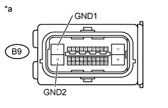
Text in Illustration *a Front view of wire harness connector
(to Skid Control ECU (Brake Actuator Assembly))
Measure the resistance according to the value(s) in the table below.
Standard Resistance Tester Connection Condition Specified Condition B9-1 (GND1) - Body ground Always Below 1 Ω B9-13 (GND2) - Body ground Always Below 1 Ω -
Reconnect the skid control ECU (brake actuator assembly) connector.
NG
REPAIR OR REPLACE HARNESS OR CONNECTOR (GND1, GND2 CIRCUIT)
OK
-
-
REPLACE VACUUM WARNING SWITCH ASSEMBLY
-
Replace the vacuum warning switch assembly Click here.
Result Result Proceed to Brake warning light illuminates A Brake warning light does not illuminate B
B
END
A
-
-
READ VALUE USING INTELLIGENT TESTER (BRAKE WARNING LIGHT)
-
Warm up the engine.
-
Turn the ignition switch off.
-
Replace the normal DLC3 cable (12 V specification) for the intelligent tester with the 24 V DLC3 cable.
Note
Be sure to use the 24 V DLC3 cable when connecting the intelligent tester to the DLC3. Using the normal DLC3 cable (12 V specification) will cause damage to the tester.
-
Connect the intelligent tester to the DLC3.
-
Turn the ignition switch to ON.
-
Turn the intelligent tester on.
-
Enter the following menus: Chassis / ABS/VSC/TRC / Data List.
-
According to the display on the intelligent tester, read the Data List.
ABS/VSC/TRC Tester Display Measurement Item/Range Normal Condition Diagnostic Note Brake Warning Light Brake warning light / OFF or ON OFF: Warning light OFF
ON: Warning light ON
- -
Check the intelligent tester display condition of the brake warning light.
Result Result Proceed to Display of the Data List remains OFF. A Display of the Data List remains ON. B
NG
REPLACE BRAKE ACTUATOR ASSEMBLY Click here
OK 
GO TO METER / GAUGE SYSTEM Click here
-