ANTI-LOCK BRAKE SYSTEM Brake Warning Light Remains ON
DESCRIPTION
If any of the following is detected, the brake warning light remains on:
-
The skid control ECU connector is disconnected from the skid control ECU.
-
The brake fluid level is insufficient.
-
The parking brake is applied.
-
EBD operation is not possible.
-
The vacuum created by the vacuum pump is below the standard level.
WIRING DIAGRAM
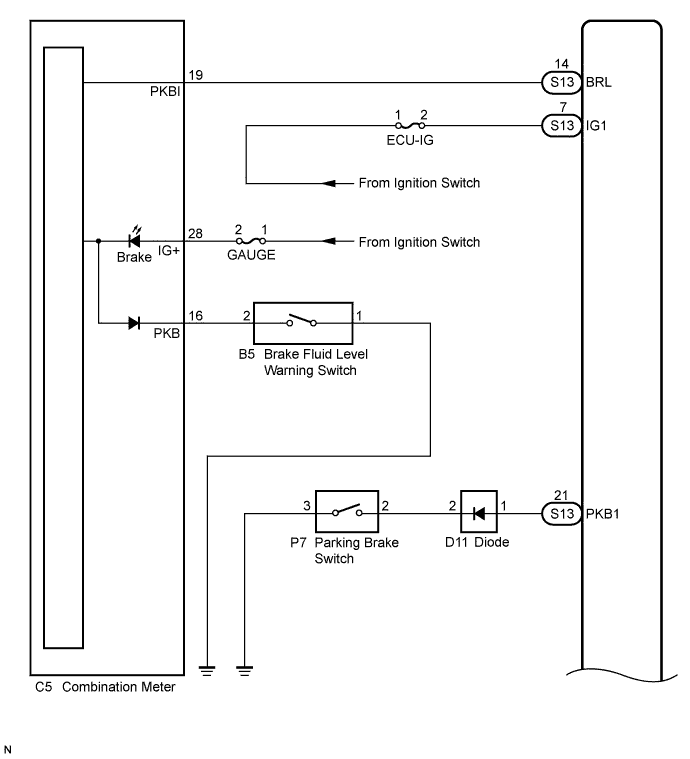
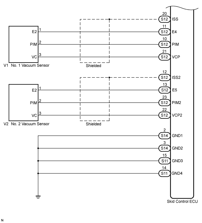
INSPECTION PROCEDURE
PROCEDURE
-
CHECK DTC
-
Check if the ABS DTC is output (See Pub. No. RM1008E, page 05-195).
Result Result Proceed to DTC is not output A DTC is output B
B 
REPAIR CIRCUIT INDICATED BY OUTPUT DTC Click here
A 
-
-
CHECK IF SKID CONTROL ECU CONNECTOR IS SECURELY CONNECTED
-
Check if the skid control ECU connector is securely connected.
OK The connector should be securely connected.
NG
CONNECT CONNECTOR TO ECU CORRECTLY
OK
-
-
CHECK BATTERY
-
Check the battery voltage.
Standard voltage 20 to 32 V
NG
CHECK OR REPLACE CHARGING SYSTEM OR BATTERY Click here
OK
-
-
INSPECT SKID CONTROL ECU (IG1 TERMINAL)
-
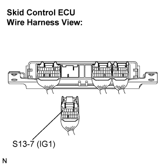
Disconnect the skid control ECU connector.
-
Turn the ignition switch to the ON position.
-
Measure the voltage according to the value(s) in the table below.
Standard voltage Tester Connection Switch Condition Specified Condition S13-7 (IG1) - Body ground Ignition switch ON 20 to 32 V
NG
REPAIR OR REPLACE HARNESS OR CONNECTOR (IG1 CIRCUIT)
OK
-
-
INSPECT SKID CONTROL ECU (GND TERMINAL)
-
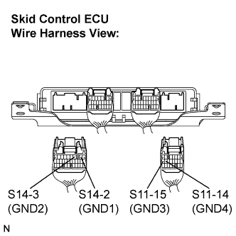
Turn the ignition switch off.
-
Disconnect the skid control ECU connectors.
-
Measure the resistance according to the value(s) in the table below.
Standard resistance Tester Connection Condition Specified Condition S14-2 (GND1) - Body ground Always Below 1 Ω S14-3 (GND2) - Body ground Always Below 1 Ω S11-15 (GND3) - Body ground Always Below 1 Ω S11-14 (GND4) - Body ground Always Below 1 Ω
NG
REPAIR OR REPLACE HARNESS OR CONNECTOR (GND CIRCUIT)
OK
-
-
READ VALUE ON INTELLIGENT TESTER (PARKING BRAKE SWITCH)
-
Reconnect the skid control ECU connectors.
-
Replace the normal DLC3 cable (12 V specification) for the intelligent tester with the 24 V DLC3 cable.
Note
Be sure to use the 24 V DLC3 cable when connecting the intelligent tester to the DLC3. Using the normal DLC3 cable (12 V specification) will cause damage to the tester.
-
Connect the intelligent tester to the DLC3.
-
Start the engine.
-
Select the Data List mode on the intelligent tester Click here.
ABS / VSC / TRC: Tester Display Measurement Item/Range Normal Condition Diagnostic Note Parking Brake SW Parking brake switch / ON or OFF ON: Parking brake applied
OFF: Parking brake released
- -
Using the intelligent tester, check the input of switch operation when the parking brake pedal is operated.
OK When the parking brake is operated, the display changes as shown above.
NG 
INSPECT PARKING BRAKE SWITCH Click here
OK
-
-
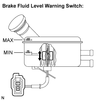
INSPECT BRAKE FLUID LEVEL WARNING SWITCH
-
Turn the ignition switch off.
-
Remove the reservoir filler cap and strainer.
-
Disconnect the brake fluid level warning switch connector.
-
Measure the resistance according to the value(s) in the table below.
Tech Tips
A float is located inside the reservoir. Its position can be changed by increasing or decreasing the level of brake fluid.
Standard resistance Tester Connection Switch Condition Specified Condition 1 - 2 Switch OFF (Float up) 1.9 to 2.1 kΩ 1 - 2 Switch ON (Float down) Below 1 Ω Tech Tips
If there is no problem after finishing the above check, adjust the brake fluid level to the MAX level.
NG
REPLACE BRAKE MASTER CYLINDER RESERVOIR SUB-ASSEMBLY (BRAKE FLUID LEVEL WARNING SWITCH)
OK
-
-
CHECK HARNESS AND CONNECTOR (COMBINATION METER - BRAKE FLUID LEVEL WARNING SWITCH)
-
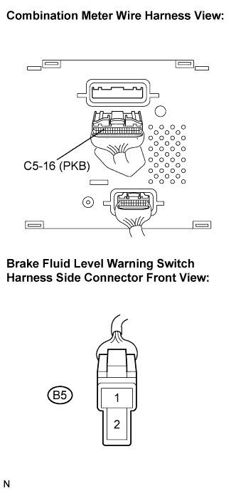
Disconnect the combination meter connector.
-
Measure the resistance according to the value(s) in the table below.
Standard resistance Tester Connection Condition Specified Condition C5-16 (PKB) - B5-2 Always Below 1 Ω C5-16 (PKB) - Body ground Always 10 kΩ or higher B5-1 - Body ground Always Below 1 Ω
NG
REPAIR OR REPLACE HARNESS OR CONNECTOR
OK
-
-
CHECK HARNESS AND CONNECTOR (SKID CONTROL ECU - COMBINATION METER)
-
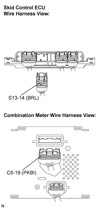
Disconnect the skid control ECU connector.
-
Measure the resistance according to the value(s) in the table below.
Standard resistance Tester Connection Condition Specified Condition S13-14 (BRL) - C5-19 (PKBI) Always Below 1 Ω S13-14 (BRL) - Body ground Always 10 kΩ or higher
NG
REPAIR OR REPLACE HARNESS OR CONNECTOR
OK
-
-
INSPECT COMBINATION METER ASSEMBLY
-
Check the combination meter.
OK The combination meter is normal. Tech Tips
-
Reinstall the connectors and restore the vehicle to its prior condition before checking the combination meter.
-
If troubleshooting has been carried out according to the Problem Symptoms Table, refer back to the table and proceed to the next step before replacing the part Click here.
-
NG
REPLACE COMBINATION METER ASSEMBLY
OK 
REPLACE SKID CONTROL ECU
-
-
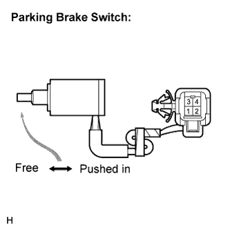
INSPECT PARKING BRAKE SWITCH
-
Turn the ignition switch off.
-
Disconnect the parking brake switch connector.
-
Measure the resistance according to the value(s) in the table below.
Standard resistance Tester Connection Switch Condition Specified Condition 2 - 3 Parking brake switch ON
(Switch pin free)
Below 1 Ω 2 - 3 Parking brake switch OFF
(Switch pin pushed in)
10 kΩ or higher
NG
REPLACE PARKING BRAKE SWITCH
OK
-
-
CHECK HARNESS AND CONNECTOR (SKID CONTROL ECU - PARKING BRAKE SWITCH)
-
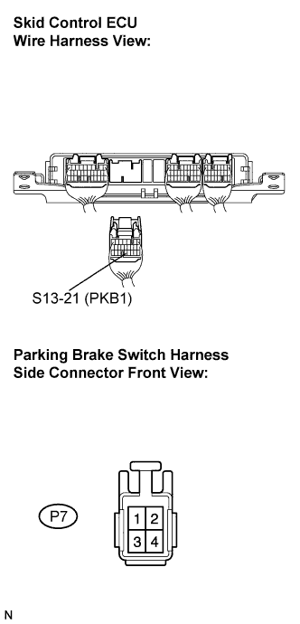
Disconnect the skid control ECU connector.
-
Measure the resistance according to the value(s) in the table below.
Standard resistance Tester Connection Condition Specified Condition S13-21 (PKB1) - P7-2 Always Below 1 Ω S13-21 (PKB1) - Body ground Always 10 kΩ or higher P7-3 - Body ground Always Below 1 Ω Tech Tips
If troubleshooting has been carried out according to the Problem Symptoms Table, refer back to the table and proceed to the next step Click here.
NG
REPAIR OR REPLACE HARNESS OR CONNECTOR
OK
REPLACE SKID CONTROL ECU
-