ANTI-LOCK BRAKE SYSTEM, Diagnostic DTC:C1277, C1278, C1415, C1416

| DTC Code | DTC Name |
|---|---|
| C1277 | Abnormal Change in Output Signal of Rear Speed Sensor RH (Test Mode DTC) |
| C1278 | Abnormal Change in Output Signal of Rear Speed Sensor LH (Test Mode DTC) |
| C1415 | Rear Speed Sensor RH Output Malfunction |
| C1416 | Rear Speed Sensor LH Output Malfunction |
DESCRIPTION
Refer to DTCs C1273, C1274, C1403 and C1404 Click here.
| DTC No. | DTC Detection Condition | Trouble Area |
|---|---|---|
| C1415 C1416 |
When any of following conditions detected:
|
|
| C1277 C1278 |
Detected only during Test Mode. |
|
Tech Tips
-
DTC C1415 and C1277 are for the rear speed sensor RH.
-
DTC C1416 and C1278 are for the rear speed sensor LH.
WIRING DIAGRAM
Refer to DTCs C1273, C1274, C1403 and C1404 Click here.
INSPECTION PROCEDURE
Note
Check the speed sensor signal after cleaning or replacement Click here.
PROCEDURE
-
CHECK REAR SPEED SENSOR INSTALLATION
-
Turn the ignition switch off.
-
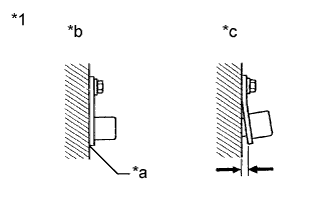
Text in Illustration *1 Rear Speed Sensor *a No clearance *b OK *c NG Check the rear speed sensor installation.
OK There is no clearance between the rear speed sensor and the rear steering knuckle.
NG 
INSTALL REAR SPEED SENSOR CORRECTLY Click here
OK 
-
-
INSPECT REAR SPEED SENSOR TIP
-
Remove the rear speed sensor Click here.
-
Check the rear speed sensor tip.
OK No scratches, oil, or foreign matter on the rear speed sensor tip. Note
If no damage to the rear speed sensor tip is found during this inspection, do not replace the rear speed sensor.
-
Reinstall the rear speed sensor.
NG
CLEAN OR REPLACE REAR SPEED SENSOR Click here
OK
-
-
INSPECT REAR SKID CONTROL ROTOR
-
Remove the rear skid control rotor Click here.
-
Check the rear skid control rotor.
OK No scratches, oil, or foreign matter on the rotors. -
Reinstall the rear skid control rotor.
NG
CLEAN OR REPLACE REAR SKID CONTROL ROTOR Click here
OK
-
-
CHECK HARNESS AND CONNECTOR (BRAKE ACTUATOR ASSEMBLY - REAR SPEED SENSOR)
-
Turn the ignition switch off.
-
Disconnect the B9 skid control ECU (brake actuator assembly) connector.
-
Disconnect the R12 and/or R11 rear speed sensor connector.
-
Measure the resistance according to the value(s) in the table below.
Standard Resistance RH Tester Connection Condition Specified Condition B9-16 (RR+) - R12-2 (RR+) Always Below 1 Ω B9-17 (RR-) - R12-1 (RR-) Always Below 1 Ω B9-16 (RR+) or R12-2 (RR+) - Body ground Always 10 kΩ or higher B9-17 (RR-) or R12-1 (RR-) - Body ground Always 10 kΩ or higher LH Tester Connection Condition Specified Condition B9-5 (RL+) - R11-2 (RL+) Always Below 1 Ω B9-4 (RL-) - R11-1 (RL-) Always Below 1 Ω B9-5 (RL+) or R11-2 (RL+) - Body ground Always 10 kΩ or higher B9-4 (RL-) or R11-1 (RL-) - Body ground Always 10 kΩ or higher -
Reconnect the B9 skid control ECU (brake actuator assembly) connector.
NG
REPAIR OR REPLACE HARNESS OR CONNECTOR
OK
-
-
INSPECT BRAKE ACTUATOR ASSEMBLY (SENSOR INPUT)
-
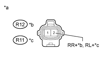
Text in Illustration *a Front view of wire harness connector
(to Rear Speed Sensor)
*b RH *c LH Turn the ignition switch to ON.
-
Measure the voltage according to the value(s) in the table below.
Standard Voltage RH Tester Connection Switch Condition Specified Condition R12-2 (RR+) - Body ground Ignition switch ON 8 to 17 V LH Tester Connection Switch Condition Specified Condition R11-2 (RL+) - Body ground Ignition switch ON 8 to 17 V -
Reconnect the R12 and/or R11 rear speed sensor connector.
NG
REPLACE BRAKE ACTUATOR ASSEMBLY Click here
OK
-
-
RECONFIRM DTC
-
Clear the DTC Click here.
-
Start the engine.
-
Drive the vehicle at a speed of 40 km/h (25 mph) or more for at least 60 seconds.
-
Check if the same DTC is recorded Click here.
Result Result Proceed to DTC is not output A DTC is output B
B 
A 
USE SIMULATION METHOD TO CHECK Click here
-
-
REPLACE REAR SPEED SENSOR
-
Replace the rear speed sensor Click here.
NEXT
-
-
RECONFIRM DTC
-
Clear the DTC Click here.
-
Start the engine.
-
Drive the vehicle at a speed of 40 km/h (25 mph) or more for at least 60 seconds.
-
Check if the same DTC is recorded Click here.
Result Result Proceed to DTC is not output A DTC is output B
B
A
END
-
-
REPLACE REAR SKID CONTROL ROTOR
-
Replace the rear skid control rotor Click here.
NEXT
-
-
RECONFIRM DTC
-
Clear the DTC Click here.
-
Start the engine.
-
Drive the vehicle at a speed of 40 km/h (25 mph) or more for at least 60 seconds.
-
Check if the same DTC is recorded Click here.
Result Result Proceed to DTC is not output A DTC is output B
B
REPLACE BRAKE ACTUATOR ASSEMBLY Click here
A
END
-