ANTI-LOCK BRAKE SYSTEM, Diagnostic DTC:C1273, C1274, C1403, C1404

| DTC Code | DTC Name |
|---|---|
| C1273 | Low Output Signal of Rear Speed Sensor RH (Test Mode DTC) |
| C1274 | Low Output Signal of Rear Speed Sensor LH (Test Mode DTC) |
| C1403 | Rear Speed Sensor RH Malfunction |
| C1404 | Rear Speed Sensor LH Malfunction |
DESCRIPTION
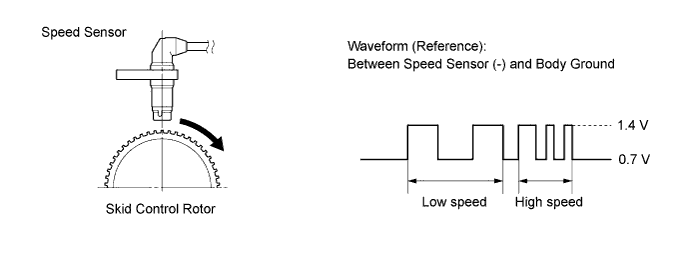
The speed sensor detects wheel speed and sends the appropriate signals to the skid control ECU (brake actuator assembly). Speed sensor rotors have 48 serrations The hall IC type speed sensor uses the frequency of output pulses to detect the vehicle speed.
Because the sensor outputs digital pulses, it can detect vehicle speeds even when the vehicle is nearly stationary.
| DTC No. | DTC Detection Condition | Trouble Area |
|---|---|---|
| C1403 C1404 |
When any of following conditions detected:
|
|
| C1273 C1274 |
Detected only during Test Mode. |
|
Tech Tips
-
DTC C1403 and C1273 are for the rear speed sensor RH.
-
DTC C1404 and C1274 are for the rear speed sensor LH.
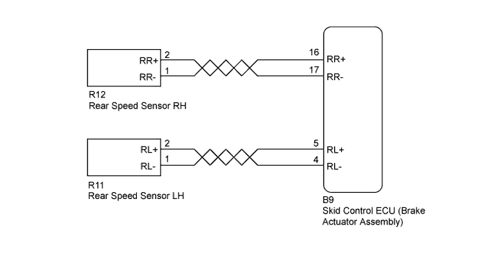
WIRING DIAGRAM
INSPECTION PROCEDURE
Note
Check the speed sensor signal after cleaning or replacement Click here.
PROCEDURE
-
READ VALUE USING INTELLIGENT TESTER (REAR SPEED SENSOR)
-
Warm up the engine.
-
Turn the ignition switch off.
-
Replace the normal DLC3 cable (12 V specification) for the intelligent tester with the 24 V DLC3 cable.
Note
Be sure to use the 24 V DLC3 cable when connecting the intelligent tester to the DLC3. Using the normal DLC3 cable (12 V specification) will cause damage to the tester.
-
Connect the intelligent tester to the DLC3.
-
Turn the ignition switch to ON.
-
Turn the intelligent tester on.
-
Enter the following menus: Chassis / ABS/VSC/TRC / Data List.
-
According to the display on the intelligent tester, read the Data List.
ABS/VSC/TRC Tester Display Measurement Item/Range Normal Condition Diagnostic Note RR Wheel Speed RR wheel speed sensor reading / Min.: 0 km/h (0 mph), Max.: 326 km/h (202 mph) Vehicle stopped:
0 km/h
When driving at constant speed: No large fluctuations RL Wheel Speed RL wheel speed sensor reading /Min.: 0 km/h (0 mph), Max.: 326 km/h (202 mph) Vehicle stopped:
0 km/h
When driving at constant speed: No large fluctuations -
Check that there is no difference between the speed value output from the speed sensor displayed on the intelligent tester and the speed value displayed on the speedometer when driving the vehicle.
Tech Tips
Factors that affect the indicated vehicle speed include tire size, tire inflation, and tire wear. The speed indicated on the speedometer has an allowable margin of error. This can be tested using a speedometer tester (calibrated chassis dynamometer). For details about testing and the margin of error, see the reference chart.
OK The speed value output from the speed sensor displayed on the intelligent tester is the same as the actual vehicle speed measured using a speedometer tester (calibrated chassis dynamometer).
NG 
CHECK HARNESS AND CONNECTOR (BRAKE ACTUATOR ASSEMBLY - REAR SPEED SENSOR) Click here
OK 
-
-
PERFORM TEST MODE INSPECTION (SIGNAL CHECK)
-
Turn the ignition switch off.
-
Perform the sensor check in the Test Mode procedure Click here.
OK All Test Mode DTCs are cleared. Result Result Proceed to NG A OK B
B
CHECK HARNESS AND CONNECTOR (BRAKE ACTUATOR ASSEMBLY - REAR SPEED SENSOR) Click here
A
-
-
CHECK REAR SPEED SENSOR INSTALLATION
-
Turn the ignition switch off.
-
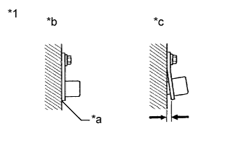
Text in Illustration *1 Rear Speed Sensor *a No clearance *b OK *c NG Check the rear speed sensor installation.
OK There is no clearance between the rear speed sensor and the rear steering knuckle.
NG 
INSTALL REAR SPEED SENSOR CORRECTLY Click here
OK
-
-
INSPECT REAR SPEED SENSOR TIP
-
Remove the rear speed sensor Click here.
-
Check the rear speed sensor tip.
OK No scratches, oil, or foreign matter on the rear speed sensor tip. Note
If no damage to the rear speed sensor tip is found during this inspection, do not replace the rear speed sensor.
-
Reinstall the rear speed sensor.
NG
CLEAN OR REPLACE REAR SPEED SENSOR Click here
OK
-
-
CHECK HARNESS AND CONNECTOR (BRAKE ACTUATOR ASSEMBLY - REAR SPEED SENSOR)
-
Turn the ignition switch off.
-
Disconnect the B9 skid control ECU (brake actuator assembly) connector.
-
Disconnect the R12 and/or R11 rear speed sensor connector.
-
Measure the resistance according to the value(s) in the table below.
Standard Resistance RH Tester Connection Condition Specified Condition B9-16 (RR+) - R12-2 (RR+) Always Below 1 Ω B9-17 (RR-) - R12-1 (RR-) Always Below 1 Ω B9-16 (RR+) or R12-2 (RR+) - Body ground Always 10 kΩ or higher B9-17 (RR-) or R12-1 (RR-) - Body ground Always 10 kΩ or higher LH Tester Connection Condition Specified Condition B9-5 (RL+) - R11-2 (RL+) Always Below 1 Ω B9-4 (RL-) - R11-1 (RL-) Always Below 1 Ω B9-5 (RL+) or R11-2 (RL+) - Body ground Always 10 kΩ or higher B9-4 (RL-) or R11-1 (RL-) - Body ground Always 10 kΩ or higher -
Reconnect the B9 skid control ECU (brake actuator assembly) connector.
NG
REPAIR OR REPLACE HARNESS OR CONNECTOR
OK
-
-
INSPECT BRAKE ACTUATOR ASSEMBLY (SENSOR INPUT)
-
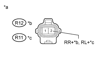
Text in Illustration *a Front view of wire harness connector
(to Rear Speed Sensor)
*b RH *c LH Turn the ignition switch to ON.
-
Measure the voltage according to the value(s) in the table below.
Standard Voltage RH Tester Connection Switch Condition Specified Condition R12-2 (RR+) - Body ground Ignition switch ON 8 to 17 V LH Tester Connection Switch Condition Specified Condition R11-2 (RL+) - Body ground Ignition switch ON 8 to 17 V -
Reconnect the R12 and/or R11 rear speed sensor connector.
NG
REPLACE BRAKE ACTUATOR ASSEMBLY Click here
OK
-
-
RECONFIRM DTC
-
Clear the DTC Click here.
-
Start the engine.
-
Drive the vehicle at a speed of 40 km/h (25 mph) or more for at least 60 seconds.
-
Check if the same DTC is recorded Click here.
Result Result Proceed to DTC is not output A DTC is output B
B
REPLACE REAR SPEED SENSOR Click here
A 
USE SIMULATION METHOD TO CHECK Click here
-
-
REPLACE REAR SPEED SENSOR
-
Replace the rear speed sensor Click here.
NEXT
-
-
RECONFIRM DTC
-
Clear the DTC Click here.
-
Start the engine.
-
Drive the vehicle at a speed of 40 km/h (25 mph) or more for at least 60 seconds.
-
Check if the same DTC is recorded Click here.
Result Result Proceed to DTC is not output A DTC is output B
B
REPLACE REAR SKID CONTROL ROTOR Click here
A
END
-
-
REPLACE REAR SKID CONTROL ROTOR
-
Replace the rear skid control rotor Click here.
NEXT
-
-
RECONFIRM DTC
-
Clear the DTC Click here.
-
Start the engine.
-
Drive the vehicle at a speed of 40 km/h (25 mph) or more for at least 60 seconds.
-
Check if the same DTC is recorded Click here.
Result Result Proceed to DTC is not output A DTC is output B
B
REPLACE BRAKE ACTUATOR ASSEMBLY Click here
A
END
-