ANTI-LOCK BRAKE SYSTEM, Diagnostic DTC:C1249, C1425

| DTC Code | DTC Name |
|---|---|
| C1249 | Open in Stop Light Switch Circuit |
| C1425 | Open in Stop Light Switch Circuit |
DESCRIPTION
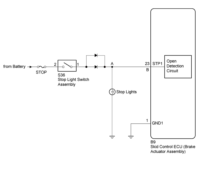
The skid control ECU (brake actuator assembly) inputs the stop light switch signal and the condition of brake operation.
The skid control ECU (brake actuator assembly) has an open detection circuit, which outputs this DTC when detecting an open in the stop light input line or the ground line of the stop light circuit with the stop light switch off (brake pedal not depressed).
| DTC No. | DTC Detection Condition | Trouble Area |
|---|---|---|
| C1249 | While the vehicle is being driven at a speed of 15 km/h (9 mph) or more, the stop light switch assembly is ON for 15 minutes or more continuously. |
|
| C1425 | When IG terminal voltage is normal, an open in the stop light switch circuit (between A-B or A-Body ground) continues for 3 seconds or more. |
WIRING DIAGRAM
INSPECTION PROCEDURE
Note
Inspect the fuses for circuits related to this system before performing the following inspection procedure.
PROCEDURE
-
CHECK STOP LIGHT SWITCH OPERATION
-
Check that the stop lights come on when the brake pedal is depressed, and go off when the brake pedal is released.
OK Stop light switch function is normal.
NG 
INSPECT STOP LIGHT CIRCUIT Click here
OK 
-
-
READ VALUE USING INTELLIGENT TESTER (STOP LIGHT SW)
-
Warm up the engine.
-
Turn the ignition switch off.
-
Replace the normal DLC3 cable (12 V specification) for the intelligent tester with the 24 V DLC3 cable.
Note
Be sure to use the 24 V DLC3 cable when connecting the intelligent tester to the DLC3. Using the normal DLC3 cable (12 V specification) will cause damage to the tester.
-
Connect the intelligent tester to the DLC3.
-
Turn the ignition switch to ON.
-
Turn the intelligent tester on.
-
Enter the following menus: Chassis / ABS/VSC/TRC / Data List.
-
According to the display on the intelligent tester, read the Data List.
ABS/VSC/TRC Tester Display Measurement Item/Range Normal Condition Diagnostic Note Stop Light SW Stop light switch / OFF or ON OFF: Brake pedal released
ON: Brake pedal depressed
- -
Check that the stop light switch display observed on the intelligent tester changes according to brake pedal operation.
OK The intelligent tester displays ON or OFF according to brake pedal operation.
NG 
INSPECT STOP LIGHT SWITCH ASSEMBLY Click here
OK
-
-
RECONFIRM DTC
-
Turn the ignition switch off.
-
Clear the DTC Click here.
-
Start the engine.
-
Depress the brake pedal several times to test the stop light circuit.
-
Check if the same DTC is recorded Click here.
Result Result Proceed to DTC is not output A DTC is output B
B
REPLACE BRAKE ACTUATOR ASSEMBLY Click here
A 
USE SIMULATION METHOD TO CHECK Click here
-
-
INSPECT STOP LIGHT SWITCH ASSEMBLY
-
Remove the stop light switch assembly Click here.
-
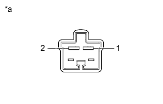
Text in Illustration *a Component without harness connected
(Stop Light Switch Assembly)
Measure the resistance according the value(s) in the table below.
Standard Resistance Tester Connection Switch Condition Specified Condition 1 - 2 Switch pin free Below 1 Ω 1 - 2 Switch pin pushed in 10 kΩ or higher
NG
REPLACE STOP LIGHT SWITCH ASSEMBLY Click here
OK
-
-
CHECK HARNESS AND CONNECTOR (STP1 TERMINAL)
-
Turn the ignition switch off.
-
Disconnect the skid control ECU (brake actuator assembly) connector.
-
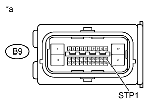
Text in Illustration *a Front view of wire harness connector
(to Skid Control ECU (Brake Actuator Assembly))
Measure the voltage according to the value(s) in the table below.
Standard Voltage Tester Connection Switch Condition Specified Condition B9-23 (STP1) - Body ground Stop light switch on
(Brake pedal depressed)
20 to 28 V B9-23 (STP1) - Body ground Stop light switch off
(Brake pedal released)
Below 1.5 V -
Reconnect the skid control ECU (brake actuator assembly) connector.
NG
REPAIR OR REPLACE HARNESS OR CONNECTOR (STP1 CIRCUIT)
OK
REPLACE BRAKE ACTUATOR ASSEMBLY Click here
-