ANTI-LOCK BRAKE SYSTEM, Diagnostic DTC:C1241/41

| DTC Code | DTC Name |
|---|---|
| C1241/41 | Low Battery Positive Voltage |
DESCRIPTION
If a malfunction is detected in the power supply circuit, the skid control ECU stores this DTC and the fail safe function prohibits ABS operation.
This DTC is stored when the IG1 terminal voltage deviates from the DTC detection condition due to a malfunction in the power supply or charging circuit such as the battery or alternator circuit, etc.
The DTC is cancelled when the IG1 terminal voltage returns to normal.
| DTC Code | DTC Detection Condition | Trouble Area |
|---|---|---|
| C1241/41 | When any of the following is detected:
|
|
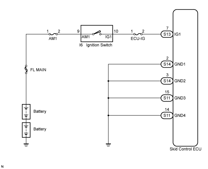
WIRING DIAGRAM
INSPECTION PROCEDURE
PROCEDURE
-
INSPECT ECU-IG FUSE
-
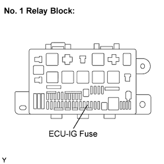
Remove the ECU-IG fuse from the No. 1 relay block.
-
Measure the resistance according to the value(s) in the table below.
Standard resistance Tester Connection Condition Specified Condition ECU-IG (15 A) fuse Always Below 1 Ω
NG 
REPLACE ECU-IG FUSE
OK 
-
-
CHECK BATTERY
-
Install the ECU-IG fuse.
-
Check the battery voltage.
Standard voltage 20 to 32 V Result Result Proceed to OK A NG (N04C-TQ) B NG (N04C-TW) C
B
CHECK OR REPLACE CHARGING SYSTEM OR BATTERY Click here
C
CHECK OR REPLACE CHARGING SYSTEM OR BATTERY Click here
A
-
-
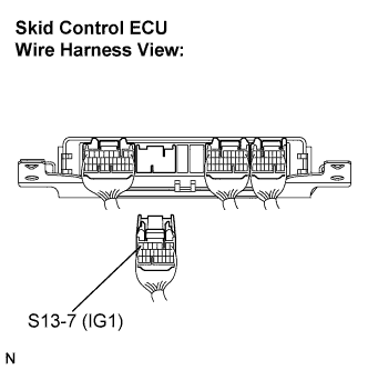
INSPECT SKID CONTROL ECU (IG1 TERMINAL)
-
Disconnect the skid control ECU connector.
-
Turn the ignition switch to the ON position.
-
Measure the voltage according to the value(s) in the table below.
Standard voltage Tester Connection Switch Condition Specified Condition S13-7 (IG1) - Body ground Ignition switch ON 20 to 32 V
NG
REPAIR OR REPLACE HARNESS OR CONNECTOR (IG1 CIRCUIT)
OK
-
-
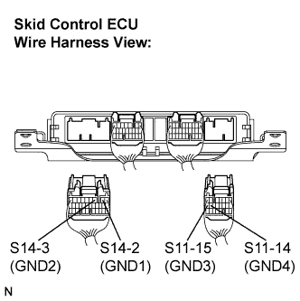
INSPECT SKID CONTROL ECU (GND TERMINAL)
-
Turn the ignition switch off.
-
Disconnect the skid control ECU connectors.
-
Measure the resistance according to the value(s) in the table below.
Standard resistance Tester Connection Condition Specified Condition S14-2 (GND1) - Body ground Always Below 1 Ω S14-3 (GND2) - Body ground Always Below 1 Ω S11-15 (GND3) - Body ground Always Below 1 Ω S11-14 (GND4) - Body ground Always Below 1 Ω
NG
REPAIR OR REPLACE HARNESS OR CONNECTOR (GND CIRCUIT)
OK
-
-
RECONFIRM DTC
-
Reconnect the skid control ECU connectors.
-
Clear the DTC (See Pub. No. RM1008E, page 05-195).
-
Drive the vehicle at the speed of 3 km/h (2 mph) or more for 10 seconds or more.
-
Check if the same DTC is recorded (See Pub. No. RM1008E, page 05-195).
Result Result Proceed to DTC (C1241/41) is not output A DTC (C1241/41) is output B Tech Tips
If troubleshooting has been carried out according to the Problem Symptoms Table, refer back to the table and proceed to the next step Click here.
B
REPLACE SKID CONTROL ECU
A 
CHECK FOR INTERMITTENT PROBLEMS (SYMPTOM SIMULATION) Click here
-