ANTI-LOCK BRAKE SYSTEM, Diagnostic DTC:C1241

| DTC Code | DTC Name |
|---|---|
| C1241 | Low Power Supply Voltage Malfunction |
DESCRIPTION
If a malfunction is detected in the power supply circuit, the skid control ECU (brake actuator assembly) stores this DTC and the fail-safe function prohibits ABS operation.
This DTC is stored when the IG terminal voltage deviates from the DTC detection condition due to a malfunction in the power supply or charging circuit such as the battery or generator circuit, etc.
The DTC is cancelled when the IG terminal voltage returns to normal.
| DTC No. | DTC Detection Condition | Trouble Area |
|---|---|---|
| C1241 | When any of following conditions detected:
|
|
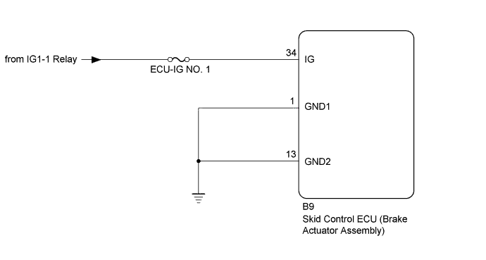
WIRING DIAGRAM
INSPECTION PROCEDURE
Note
Inspect the fuses for circuits related to this system before performing the following inspection procedure.
PROCEDURE
-
INSPECT BATTERY
-
Inspect the battery voltage.
Standard voltage 20 to 28 V
NG 
CHECK OR REPLACE CHARGING SYSTEM OR BATTERY Click here
OK 
-
-
READ VALUE USING INTELLIGENT TESTER (IG1 VOLTAGE VALUE)
-
Warm up the engine.
-
Turn the ignition switch off.
-
Replace the normal DLC3 cable (12 V specification) for the intelligent tester with the 24 V DLC3 cable.
Note
Be sure to use the 24 V DLC3 cable when connecting the intelligent tester to the DLC3. Using the normal DLC3 cable (12 V specification) will cause damage to the tester.
-
Connect the intelligent tester to the DLC3.
-
Turn the ignition switch to ON.
-
Turn the intelligent tester on.
-
Enter the following menus: Chassis / ABS/VSC/TRC / Data List.
-
According to the display on the intelligent tester, perform the Data List.
ABS/VSC/TRC Tester Display Measurement Item/Range Normal Condition Diagnostic Note IG1 Voltage Value IG voltage value / Min.: 0.00 V, Max.: 40.00 V - Changes in proportion to auxiliary battery voltage OK 20 to 28 V
NG
REPLACE BRAKE ACTUATOR ASSEMBLY Click here
OK
-
-
CHECK HARNESS AND CONNECTOR (IG TERMINAL)
-
Turn the ignition switch off.
-
Disconnect the skid control ECU (brake actuator assembly) connector.
-
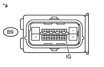
Text in Illustration *a Front view of wire harness connector
(to Skid Control ECU (Brake Actuator Assembly))
Measure the voltage according to the value(s) in the table below.
Standard Voltage Tester Connection Switch Condition Specified Condition B9-34 (IG) - Body ground Ignition switch ON 20 to 28 V
NG
REPAIR OR REPLACE HARNESS OR CONNECTOR (IG CIRCUIT)
OK
-
-
CHECK HARNESS AND CONNECTOR (GND1, GND2 TERMINAL)
-
Turn the ignition switch off.
-
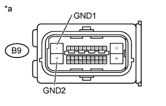
Text in Illustration *a Front view of wire harness connector
(to Skid Control ECU (Brake Actuator Assembly))
Measure the resistance according to the value(s) in the table below.
Standard Resistance Tester Connection Condition Specified Condition B9-1 (GND1) - Body ground Always Below 1 Ω B9-13 (GND2) - Body ground Always Below 1 Ω -
Reconnect the skid control ECU (brake actuator assembly) connector.
NG
REPAIR OR REPLACE HARNESS OR CONNECTOR (GND1, GND2 CIRCUIT)
OK
-
-
RECONFIRM DTC
-
Clear the DTC Click here.
-
Start the engine.
-
Drive the vehicle at a speed of 20 km/h (12 mph) or more for 30 seconds or more.
-
Check if the same DTC is recorded Click here.
Result Result Proceed to DTC is not output A DTC is output B
B
REPLACE BRAKE ACTUATOR ASSEMBLY Click here
A 
USE SIMULATION METHOD TO CHECK Click here
-