ANTI-LOCK BRAKE SYSTEM TS and CG Terminal Circuit
DESCRIPTION
In the Test Mode (signal check), a malfunction of the speed sensor that cannot be detected when the vehicle is stopped can be detected while driving.
Transition to the sensor check mode can be performed by connecting terminals TS and CG of the DLC3 and turning the ignition switch from off to ON.
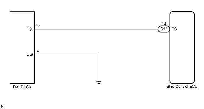
WIRING DIAGRAM
INSPECTION PROCEDURE
PROCEDURE
-
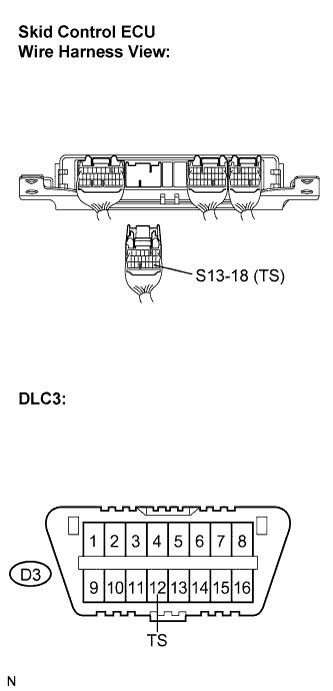
CHECK HARNESS AND CONNECTOR (SKID CONTROL ECU - TS of DLC3)
-
Disconnect the skid control ECU connector.
-
Measure the resistance according to the value(s) in the table below.
Standard resistance Tester Connection Condition Specified Condition S13-18 (TS) - D3-12 (TS) Always Below 1 Ω
NG 
REPAIR OR REPLACE HARNESS OR CONNECTOR
OK 
-
-
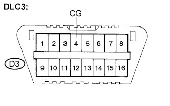
CHECK HARNESS AND CONNECTOR (CG of DLC3 - BODY GROUND)
-
Measure the resistance according to the value(s) in the table below.
Standard resistance Tester Connection Condition Specified Condition D3-4 (CG) - Body ground Always Below 1 Ω
NG
REPAIR OR REPLACE HARNESS OR CONNECTOR
OK
-
-
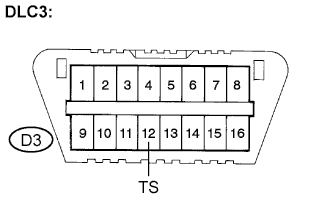
CHECK HARNESS AND CONNECTOR (TS of DLC3 - BODY GROUND)
-
Measure the resistance according to the value(s) in the table below.
Standard resistance Tester Connection Condition Specified Condition D3-12 (TS) - Body ground Always 10 kΩ or higher Tech Tips
If troubleshooting has been carried out according to the Problem Symptoms Table, refer back to the table and proceed to the next step before replacing the part Click here.
NG
REPAIR OR REPLACE HARNESS OR CONNECTOR
OK 
REPLACE SKID CONTROL ECU
-