ANTI-LOCK BRAKE SYSTEM DIAGNOSIS SYSTEM

-
DESCRIPTION
When troubleshooting a vehicle with the diagnosis system, the only difference from the usual troubleshooting procedure is connecting the intelligent tester to the vehicle and reading various data output from the vehicle's skid control ECU.
The skid control ECU records DTCs when the computer detects a malfunction in the computer itself or in its circuits.
To check the DTCs, connect the intelligent tester to the DLC3 on the vehicle. The intelligent tester enables you to erase the DTCs, activate the various actuators, and check the Data List.
Note
Be sure to use the 24 V DLC3 cable when connecting the intelligent tester to the DLC3. Using the normal DLC3 cable (12 V specification) will cause damage to the tester.
-
Check the battery voltage.
If the voltage is below 20 V, recharge the battery before proceeding.
-
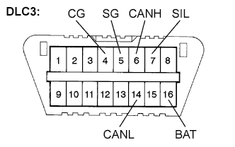
Check the DLC3.
The ECU uses ISO 15765-4 for communication. The terminal arrangement of the DLC3 complies with ISO 15031-3 and matches the ISO 15765-4 format.
If the result is not as specified, the DLC3 may have a malfunction. Repair or replace the harness and connector.
Verify the conditions listed in the table below.
Terminal No. (Symbols) Terminal Description Condition Specified Condition 7 (SIL) - 5 (SG) Bus "+" line During transmission Pulse generation 4 (CG) - Body ground Chassis ground Always Below 1 Ω 5 (SG) - Body ground Signal ground Always Below 1 Ω 16 (BAT) - Body ground Battery positive Always 20 to 32 V 6 (CANH) - 14 (CANL) CAN bus line Ignition switch off* 54 to 69 Ω 6 (CANH) - 4 (CG) HIGH-level CAN bus line Ignition switch off* 200 Ω or higher 14 (CANL) - 4 (CG) LOW-level CAN bus line Ignition switch off* 200 Ω or higher 6 (CANH) - 16 (BAT) HIGH-level CAN bus line Ignition switch off* 6 kΩ or higher 14 (CANL) - 16 (BAT) LOW-level CAN bus line Ignition switch off* 6 kΩ or higher Note
*: Before measuring the resistance, leave the vehicle as is for at least 1 minute and do not operate the ignition switch, any other switches or the doors.
Tech Tips
Connect the cable of the intelligent tester to the DLC3, turn the ignition switch to the ON position and attempt to use the tester. If the display indicates that a communication error has occurred, there is a problem either with the vehicle or with the tester.
Note
Be sure to use the 24 V DLC3 cable when connecting the intelligent tester to the DLC3. Using the normal DLC3 cable (12 V specification) will cause damage to the tester.
-
If communication is normal when the tester is connected to another vehicle, inspect the DLC3 on the original vehicle.
-
If communication is still not possible when the tester is connected to another vehicle, the problem may be in the tester itself. Consult the Service Department listed in the tester operator's manual.
-
-
-
DIAGNOSIS
-
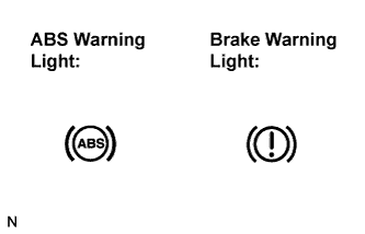
If the skid control ECU detects a malfunction, the ABS warning and the brake warning lights will come on to warn the driver.
The table below indicates which lights will come on when there is a malfunction in a particular function.
Item / Trouble Area ABS EBD ABS warning light ○ ○ Brake warning light - ○ ○: Light ON
-: Light OFF
-
The DTCs are simultaneously stored in the memory. The DTCs can be read by connecting the SST between terminals TC and CG of the DLC3 and observing the blinking pattern of the ABS warning light, or by connecting the intelligent tester.
-
This system has a Test Mode (signal check) function Click here.
The DTC can be read by connecting the intelligent tester and observing the blinking pattern of the ABS warning light.
-
-
-
WARNING LIGHT INITIAL CHECK
-
Release the parking brake.
Note
When releasing the parking brake, set chocks to hold the vehicle for safety.
Tech Tips
When the parking brake is applied, the level of the brake fluid is low or the vacuum is low, the brake warning light comes on.
-
When the ignition switch is turned to the ON position, check that the ABS and brake warning lights come on for approximately 3 seconds.
Tech Tips
If the warning light and indicator light check result is not normal, proceed to troubleshooting for the ABS and brake warning light circuits.
If the indicator remains on, proceed to troubleshooting for the light circuit below.
Trouble Area See procedure ABS warning light circuit (Remains on) Brake warning light circuit (Remains on)
-
-
SYMPTOM SIMULATION
Tech Tips
The most difficult case in troubleshooting is when no symptoms occur. In such cases, a thorough customer problem analysis must be carried out. Then the same or similar conditions and environment in which the problem occurred in the customer's vehicle should be reproduced. No matter how experienced or skilled a technician may be, if he proceeds to troubleshooting without confirming the problem symptoms, he will likely overlook something important and make a wrong guess at some points in the repair operation. This leads to a standstill in troubleshooting.
-
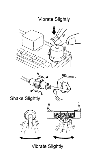
Vibration method: When vibration seems to be the major cause.
Tech Tips
Perform the simulation method only during the primary check period (for approximately 6 seconds after the ignition switch is turned to the ON position).
-
Slightly vibrate the part of the sensor considered to be the problem cause with your fingers and check whether the malfunction occurs.
-
Slightly shake the connector vertically and horizontally.
Tech Tips
Shaking the relays too strongly may result in open relays.
-
Slightly shake the wire harness vertically and horizontally. The connector joint and fulcrum of the vibration are the major areas to be checked thoroughly.
-
-