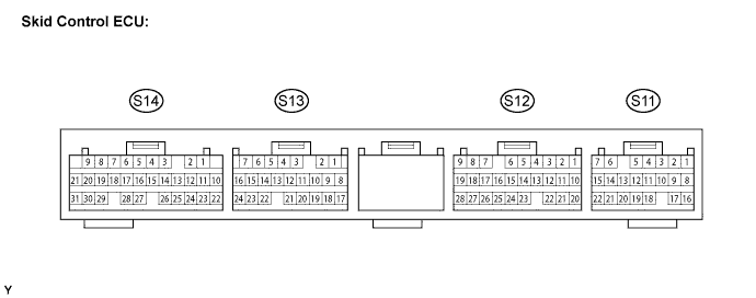
ANTI-LOCK BRAKE SYSTEM TERMINALS OF ECU

-
CHECK BATTERY VOLTAGE
-
Check the battery voltage.
-
-
INSPECT SKID CONTROL ECU
-
Measure the voltage between each terminal and the body ground.
-
Connect the intelligent tester to the DLC3, and check the communication condition with the skid control ECU.
-
Using an oscilloscope, check that the pulse generates between each terminal and the body ground.
Note
-
Be sure to use the 24 V DLC3 cable when connecting the intelligent tester to the DLC3. Using the normal DLC3 cable (12 V specification) will cause damage to the tester.
-
Inspection should be performed from the back of the connector with the connector connected to the skid control ECU.
Tech Tips
Inspect the ECU from the wire harness side while the connector is connected.
Terminal No. (Symbols) Wiring Color Terminal Description Condition Specified Condition S11-1 (SRLR) - Body ground R-Y - Body ground Rear decrease solenoid LH output Approx. 3 seconds after turning ignition switch ON 20 to 32 V S11-2 (SM1-) - Body ground W-R - Body ground Front linear solenoid (-) output Approx. 3 seconds after turning ignition switch ON Below 3 V S11-3 (SM1+) - Body ground B-Y - Body ground Front linear solenoid (+) output Approx. 3 seconds after turning ignition switch ON Below 3 V S11-4 (SM2-) - Body ground W-L - Body ground Rear linear solenoid (-) output Approx. 3 seconds after turning ignition switch ON Below 3 V S11-5 (SM2+) - Body ground W-G - Body ground Rear linear solenoid (+) output Approx. 3 seconds after turning ignition switch ON Below 3 V S11-6 (AST) - Body ground BR-B - Body ground Solenoid relay test input Approx. 3 seconds after turning ignition switch ON 20 to 32 V S11-7 (SRLH) - Body ground L-O - Body ground Rear holding solenoid LH output Approx. 3 seconds after turning ignition switch ON 20 to 32 V S11-8 (SFRR) - Body ground R-W - Body ground Front decrease solenoid RH output Approx. 3 seconds after turning ignition switch ON 20 to 32 V S11-14 (GND4) - Body ground W-B - Body ground Skid control ECU ground 4 Always Below 1 Ω S11-15 (GND3) - Body ground W-B - Body ground Skid control ECU ground 3 Always Below 1 Ω S11-16 (SFRH) - Body ground Y - Body ground Front holding solenoid RH output Approx. 3 seconds after turning ignition switch ON 20 to 32 V S12-10 (PIM) - Body ground W - Body ground Vacuum sensor input Engine idling 0.5 to 4 V S12-11 (E4) - Body ground R - Body ground Vacuum sensor ground Always Below 1 Ω S12-12 (ISS2) - Body ground Shielded - Body ground Vacuum sensor 2 shielded ground Always Below 1 Ω S12-13 (E5) - Body ground V - Body ground Vacuum sensor 2 ground Always Below 1 Ω S12-14 (PSS) - Body ground Shielded - Body ground Master cylinder pressure sensor shielded ground Always Below 1 Ω S12-15 (E2) - Body ground R - Body ground Master cylinder pressure sensor ground Always Below 1 Ω S12-20 (ISS) - Body ground Shielded - Body ground Vacuum sensor shielded ground Always Below 1 Ω S12-21 (VCP) - Body ground B - Body ground Vacuum sensor power supply output Ignition switch ON 4.75 to 5.25 V S12-22 (VCP2) - Body ground O - Body ground Vacuum sensor 2 power supply output Ignition switch ON 4.75 to 5.25 V S12-23 (PIM2) - Body ground LG - Body ground Vacuum sensor 2 input Engine idling 0.5 to 4 V S12-24 (VCM) - Body ground B - Body ground Master cylinder pressure sensor power supply output Ignition switch ON 4.75 to 5.25 V S12-25 (PMC) - Body ground W - Body ground Master cylinder pressure sensor input Ignition switch ON, brake pedal released 0.3 to 0.7 V S13-1 (STP) - Body ground R - Body ground Stop light switch input Stop light switch ON → OFF (Brake pedal depressed → released) 16 to 32 V → Below 3 V S13-6 (WA) - Body ground R-Y - Body ground ABS warning light output Ignition switch off → ON 7 to 18 V for approx. 3 seconds → Below 3 V S13-7 (IG1) - Body ground B-R - Body ground IG1 power supply Ignition switch ON 20 to 32 V S13-10 (EXO) - Body ground V-R - Body ground Exhaust brake request output Ignition switch ON 18 to 32 V S13-14 (BRL) - Body ground P-B - Body ground Brake warning light output Ignition switch off → ON 7 to 25 V for approx. 3 seconds → Below 2 V S13-15 (RR-) - Body ground BR - Body ground Rear wheel speed sensor RH (-) input Ignition switch off Below 1 Ω S13-16 (RR+) - Body ground Y - Body ground Rear wheel speed sensor RH (+) input Vehicle speed input Pulse generation
(see waveform 1)
S13-18 (TS) - Body ground P - Body ground Sensor check activation input Ignition switch ON, terminals TS and CG of DLC3 connected → disconnected Below 3 V → 10 to 32 V S13-19 (TC) - Body ground R-L - Body ground Diagnosis activation input Ignition switch ON, terminals TC and CG of DLC3 connected → disconnected Below 3 V → 20 to 32 V S13-21 (PKB1) - Body ground B-Y - Body ground Parking brake switch 1 input Ignition switch ON, parking brake switch ON → OFF Below 3 V → 10 to 32 V S13-22 (RL+) - Body ground P - Body ground Rear wheel speed sensor LH (+) input Vehicle speed input Pulse generation
(see waveform 1)
S13-23 (RL-) - Body ground L - Body ground Rear wheel speed sensor LH (-) input Ignition switch off Below 1 Ω S13-24 (RSS) - Body ground BR - Body ground Rear wheel speed sensor shielded ground Ignition switch off Below 1 Ω S14-1 (R+) - Body ground V-G - Body ground Relay power supply Ignition switch ON 20 to 32 V S14-2 (GND1) - Body ground W-B - Body ground Skid control ECU ground 1 Always Below 1 Ω S14-3 (GND2) - Body ground W-B - Body ground Skid control ECU ground 2 Always Below 1 Ω S14-6 (SRM1) - Body ground B-W - Body ground SRM1 solenoid output Approx. 3 seconds after turning ignition switch ON 20 to 32 V S14-8 (SFLH) - Body ground LG-B - Body ground Front holding solenoid LH output Approx. 3 seconds after turning ignition switch ON 20 to 32 V S14-9 (SFLR) - Body ground R-G - Body ground Front decrease solenoid LH output Approx. 3 seconds after turning ignition switch ON 20 to 32 V S14-12 (MR) - Body ground B-O - Body ground Motor relay output Approx. 3 seconds after turning ignition switch ON 20 to 32 V S14-13 (D/G) - Body ground W - Body ground Diagnosis tester communication line Using intelligent tester Communication possible S14-18 (MT) - Body ground BR-W - Body ground Motor relay test input Approx. 3 seconds after turning ignition switch ON Below 1.7 V S14-20 (SRRH) - Body ground P-G - Body ground Rear holding solenoid RH output Approx. 3 seconds after turning ignition switch ON 20 to 32 V S14-21 (SRM2) - Body ground B-R - Body ground SRM2 solenoid output Approx. 3 seconds after turning ignition switch ON 20 to 32 V S14-24 (SR) - Body ground R-G - Body ground Solenoid relay output Approx. 3 seconds after turning ignition switch ON Below 3 V S14-25 (FR-) - Body ground W - Body ground Front wheel speed sensor RH (-) input Ignition switch off Below 1 Ω S14-26 (FR+) - Body ground B - Body ground Front wheel speed sensor RH (+) input Vehicle speed input Pulse generation
(see waveform 1)
S14-27 (FL+) - Body ground R - Body ground Front wheel speed sensor LH (+) input Vehicle speed input Pulse generation
(see waveform 1)
S14-28 (FL-) - Body ground G - Body ground Front wheel speed sensor LH (-) input Ignition switch off Below 1 Ω S14-29 (FSS) - Body ground BR - Body ground Front wheel speed sensor shielded ground Ignition switch off Below 1 Ω S14-30 (SRRR) - Body ground LG - Body ground Rear decrease solenoid output Approx. 3 seconds after turning ignition switch ON 20 to 32 V -
-
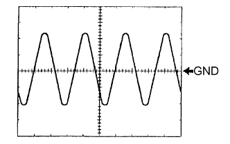
Waveform 1 (Reference): Using an oscilloscope:
Item Condition Tool setting 1 V/DIV., 2 ms/DIV. Vehicle condition While driving at approximately 30 km/h (18 mph). Tech Tips
As the vehicle speed (tire rotating speed) becomes faster, the cycle becomes shorter and output voltage larger.
-