ANTI-LOCK BRAKE SYSTEM TEST MODE PROCEDURE

-
TEST MODE PROCEDURE (SIGNAL CHECK)
Tech Tips
-
If the ignition switch is turned from ON to ACC or off during Test Mode (signal check), DTCs recorded during the signal check function will be cleared.
-
During Test Mode (signal check), the skid control ECU (brake actuator assembly) records all DTCs of the signal check function. By performing the Test Mode (signal check), the codes are cleared if a normal condition is confirmed. The remaining codes are the codes where an abnormality was found.
-
Procedure to enter Test Mode (Using Intelligent Tester).
-
Start the engine.
Tech Tips
Idle the engine for 20 seconds or more to ensure high vacuum in the vacuum booster.
-
Turn the ignition switch off.
Tech Tips
When the ignition switch is off, to prevent vacuum loss, do not depress the brake pedal.
-
Check that the steering wheel is in the straight ahead position.
-
Check that the shift lever is in neutral and apply the parking brake.
-
Replace the normal DLC3 cable (12 V specification) for the intelligent tester with the 24 V DLC3 cable.
Note
Be sure to use the 24 V DLC3 cable when connecting the intelligent tester to the DLC3.
Using the normal DLC3 cable (12 V specification) will cause damage to the tester.
-
Connect the intelligent tester to the DLC3.
-
Turn the ignition switch to ON.
-
Turn the tester on.
-
Enter the following menus: Chassis / ABS/VSC/ TRC / Signal Check.
-
Check that the ABS warning light comes on for several seconds and then blinks in Test Mode.
Note
Do not depress the brake pedal until the entry of the Test Mode is confirmed.
-
If the Test Mode display cannot be confirmed, start the engine and confirm that Test Mode display is shown after several seconds.
Tech Tips
-
If the negative pressure in the brake booster is insufficient, the brake warning light may come on and remain on without showing the Test Mode display.
-
If the ABS warning light does not blink, inspect the 12 (TS) and 4 (CG) terminal circuit and ABS warning light circuit.
Trouble Area See procedure TS and CG terminal circuit ABS warning light circuit (Remains on) ABS warning light circuit (Does not come on) -
-
-
Procedure to enter Test Mode (Using SST Check Wire).
-
Start the engine.
Tech Tips
Idle the engine for 20 seconds or more to ensure high vacuum in the vacuum booster.
-
Turn the ignition switch off.
Tech Tips
When the ignition switch is off, to prevent vacuum loss, do not depress the brake pedal.
-
Check that the steering wheel is in the straight ahead position.
-
Check that the shift lever is in neutral and apply the parking brake.
-
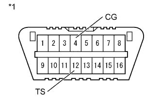
Text in Illustration *1 DLC3 Using SST, connect terminals 12 (TS) and 4 (CG) of the DLC3.
- SST
- 09843-18040
-
Turn the ignition switch to ON.
-
Check that the ABS warning light comes on for several seconds and then blinks in Test Mode.
Note
Do not depress the brake pedal until the entry of the Test Mode is confirmed.
-
If the Test Mode display cannot be confirmed, start the engine and confirm that Test Mode display is shown after several seconds.
Tech Tips
-
If the negative pressure in the brake booster is insufficient, the brake warning light may come on and remain on without showing the Test Mode display.
-
If the ABS warning light does not blink, inspect the 12 (TS) and 4 (CG) terminal circuit and ABS warning light circuit.
-
-
-
MASTER CYLINDER PRESSURE SENSOR CHECK
Tech Tips
If the engine is running, stop the engine once and then turn the ignition switch to the ON position.
-
Leave the vehicle stationary and release the brake pedal for 1 second or more, and depress the brake pedal with a force of 186 N (19 kgf, 42 lbf) or more.
-
Check that the ABS warning light comes on.
-
Depress the brake pedal for 1 second with the ABS warning light illuminated and release it.
-
Check that the blinking pattern of the ABS warning light returns to the pattern shown in Test Mode.
Note
-
Do not depress the brake pedal several times.
-
If the ABS warning light does not come on although the brake pedal is depressed, the master cylinder pressure sensor may be defective.
-
-
-
VACUUM SENSOR CHECK
Tech Tips
If the engine is running, stop the engine once and then turn the ignition switch to the ON position.
-
Depress the brake pedal several times.
-
Check that the ABS warning light comes on.
Note
-
If the ABS warning light does not come on after depressing the brake pedal continuously, the vacuum sensor may be defective.
-
When the parking brake is released, the vacuum warning buzzer may sound.
-
Soon after the warning light changes from blinking to staying on, stop the pumping operation.
-
-
-
SPEED SENSOR CHECK
-
Drive the vehicle straight ahead. Accelerate the vehicle to a speed of 45 km/h (28 mph) or more for several seconds and check that the ABS warning light goes off.
Tech Tips
-
The sensor check may not be completed if wheel spin occurs.
-
The ABS warning light blinks when the sensor check has been completed and the brake pedal is depressed.
-
The ABS warning light comes on immediately after a malfunction has been detected during the speed sensor check.
-
-
Stop the vehicle.
Note
-
The speed sensor check may not be completed if the speed sensor check is started while turning the steering wheel or spinning the wheels
-
If the sensor check has not been completed, the ABS warning light blinks during driving and the ABS system does not operate.
Tech Tips
When the sensor check has been completed, the ABS warning light goes off during driving and blinks in the Test Mode pattern while the vehicle is stationary.
-
-
-
END OF SENSOR CHECK
-
If the sensor check is completed, the ABS warning light blinks (Test Mode) when the vehicle stops and the ABS warning light is off while the vehicle is being driven.
Note
-
When the master cylinder pressure sensor, vacuum sensor, and speed sensor checks are completed, the sensor check is completed.
-
If the sensor check is not completed, the ABS warning light blinks even while the vehicle is being driven and the ABS does not operate.
-
-
-
READ DTC OF SIGNAL CHECK FUNCTION (Using Intelligent Tester)
-
Read the DTC(s) by following the tester screen.
Note
-
If only the DTCs are displayed, repair the malfunction area and clear the DTCs.
-
If the DTCs or Test Mode codes (DTC of signal check function) are displayed, repair the malfunction area, clear the DTCs, and perform Test Mode inspection.
-
-
See the list of DTCs (See procedure "Sensor Check DTCs").
-
Turn the ignition switch off and disconnect the Intelligent Tester.
-
-
READ DTC OF SIGNAL CHECK FUNCTION (Using SST Check Wire)
-
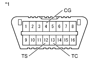
Text in Illustration *1 DLC3 Using SST, connect terminals 13 (TC), 12 (TS) and 4 (CG) of the DLC3.
- SST
- 09843-18040
-
Count the number of blinks of the ABS warning light.
Tech Tips
-
If only the DTCs are displayed, repair the malfunction area and clear the DTCs.
-
If the DTCs or Test Mode codes (DTC of signal check function) are displayed, repair the malfunction area, clear the DTCs, and perform Test Mode inspection.
-
When the system is operating correctly, each light will blink continuously in a pattern of 0.25 seconds on, then 0.25 seconds off.
-
When one DTC is output, each light will output the same code at 4 second intervals. (For example, Code 21 would be output as 2 flashes, a 1.5 second pause, and then 1 flash)
-
When 2 or more DTCs are output, each light will output a different code at 2.5 second intervals, and when all codes have been output, there will be a 4 second pause and the sequence will repeat.
-
When multiple codes are set, they are output in order starting with the lowest DTC number.
Note
-
If only the DTCs are displayed, repair the malfunction area and clear the DTCs.
-
If the DTCs or Test Mode codes (DTC of signal check function) are displayed, repair the malfunction area, clear the DTCs, and perform Test Mode inspection.
-
-
See the list of DTCs (See procedure "Sensor Check DTCs").
-
After performing the check, disconnect SST from terminals 13 (TC), 12 (TS) and 4 (CG) of the DLC3, and turn the ignition switch off.
-
Turn the ignition switch to ON to cancel Test Mode.
Tech Tips
-
If the ignition switch is not turned to ON after SST is removed from the DLC3, the previous Test Mode will continue.
-
If the ignition switch is turned to ON with terminals 12 (TS) and 4 (CG) shorted, the previous Test Mode will continue.
-
-
-
DTC OF TEST MODE (SIGNAL CHECK) FUNCTION
Sensor Check DTCs DTC Code Detection Item See page C1271/71 Low output signal of front speed sensor RH C1272/72 Low output signal of front speed sensor LH C1273/73 Low output signal of rear speed sensor RH C1274/74 Low output signal of rear speed sensor LH C1275/75 Abnormal change in output signal of front speed sensor RH C1276/76 Abnormal change in output signal of front speed sensor LH C1277/77 Abnormal change in output signal of rear speed sensor RH C1278/78 Abnormal change in output signal of rear speed sensor LH C1281/81 Master cylinder pressure sensor output malfunction C1285/85 Vacuum sensor output malfunction Tech Tips
The codes in this table are output only in Test Mode (signal check).
-