ANTI-LOCK BRAKE SYSTEM, Diagnostic DTC:C0226/21, C0236/22, C0246/23, C0256/24, C1227/27

| DTC Code | DTC Name |
|---|---|
| C0226/21 | SFR Solenoid Circuit |
| C0236/22 | SFL Solenoid Circuit |
| C0246/23 | SRR Solenoid Circuit |
| C0256/24 | SRL Solenoid Circuit |
| C1227/27 | SRM Solenoid Circuit |
DESCRIPTION
These solenoids turn on when signals are received from the skid control ECU and control the pressure acting on the wheel cylinders to control the braking force.
| DTC Code | DTC Detection Condition | Trouble Area |
|---|---|---|
| C0226/21 C0236/22 C0246/23 C0256/24 C1227/27 |
When AST terminal voltage is 20 to 32 V, an open or short in the solenoid circuit continues for 0.05 seconds or more. |
|
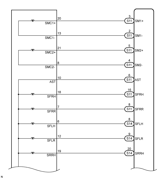
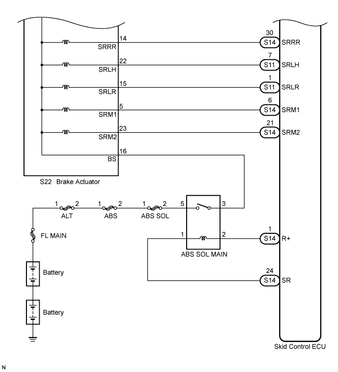
WIRING DIAGRAM
INSPECTION PROCEDURE
Tech Tips
When C0278/11 and/or C0279/12 is output together with C0226/21, C0236/22, C0246/23, C0256/24, and/or C1227/27, inspect and repair the trouble areas indicated by C0278/11 and/or C0279/12 first Click here.
PROCEDURE
-
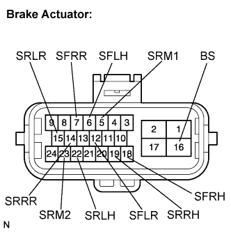
INSPECT BRAKE ACTUATOR ASSEMBLY
-
Disconnect the brake actuator connector.
-
Measure the resistance according to the value(s) in the table below.
Standard resistance Tester Connection Condition Specified Condition 16 (BS) - 18 (SFRH) Always 31.7 to 35.7 Ω at 25°C (77°F) 18 (SFRH) - Body ground Always 10 kΩ or higher 16 (BS) - 6 (SFLH) Always 31.7 to 35.7 Ω at 25°C (77°F) 6 (SFLH) - Body ground Always 10 kΩ or higher 16 (BS) - 19 (SRRH) Always 31.7 to 35.7 Ω at 25°C (77°F) 19 (SRRH) - Body ground Always 10 kΩ or higher 16 (BS) - 22 (SRLH) Always 31.7 to 35.7 Ω at 25°C (77°F) 22 (SRLH) - Body ground Always 10 kΩ or higher 16 (BS) - 7 (SFRR) Always 15.9 to 17.9 Ω at 25°C (77°F) 7 (SFRR) - Body ground Always 10 kΩ or higher 16 (BS) - 12 (SFLR) Always 15.9 to 17.9 Ω at 25°C (77°F) 12 (SFLR) - Body ground Always 10 kΩ or higher 16 (BS) - 14 (SRRR) Always 15.9 to 17.9 Ω at 25°C (77°F) 14 (SRRR) - Body ground Always 10 kΩ or higher 16 (BS) - 15 (SRLR) Always 15.9 to 17.9 Ω at 25°C (77°F) 15 (SRLR) - Body ground Always 10 kΩ or higher 16 (BS) - 5 (SRM1) Always 20.5 to 23.5 Ω at 25°C (77°F) 5 (SRM1) - Body ground Always 10 kΩ or higher 16 (BS) - 23 (SRM2) Always 20.5 to 23.5 Ω at 25°C (77°F) 23 (SRM2) - Body ground Always 10 kΩ or higher
NG 
REPLACE BRAKE ACTUATOR ASSEMBLY Click here
OK 
-
-
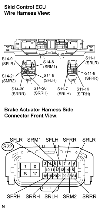
CHECK HARNESS AND CONNECTOR (SKID CONTROL ECU - BRAKE ACTUATOR)
-
Disconnect the skid control ECU connectors.
-
Measure the resistance according to the value(s) in the table below.
Standard resistance Tester Connection Condition Specified Condition S11-16 (SFRH) - S22-18 (SFRH) Always Below 1 Ω S11-16 (SFRH) - Body ground Always 10 kΩ or higher S11-8 (SFRR) - S22-7 (SFRR) Always Below 1 Ω S11-8 (SFRR) - Body ground Always 10 kΩ or higher S14-8 (SFLH) - S22-6 (SFLH) Always Below 1 Ω S14-8 (SFLH) - Body ground Always 10 kΩ or higher S14-9 (SFLR) - S22-12 (SFLR) Always Below 1 Ω S14-9 (SFLR) - Body ground Always 10 kΩ or higher S14-20 (SRRH) - S22-19 (SRRH) Always Below 1 Ω S14-20 (SRRH) - Body ground Always 10 kΩ or higher S14-30 (SRRR) - S22-14 (SRRR) Always Below 1 Ω S14-30 (SRRR) - Body ground Always 10 kΩ or higher S11-7 (SRLH) - S22-22 (SRLH) Always Below 1 Ω S11-7 (SRLH) - Body ground Always 10 kΩ or higher S11-1 (SRLR) - S22-15 (SRLR) Always Below 1 Ω S11-1 (SRLR) - Body ground Always 10 kΩ or higher S14-6 (SRM1) - S22-5 (SRM1) Always Below 1 Ω S14-6 (SRM1) - Body ground Always 10 kΩ or higher S14-21 (SRM2) - S22-23 (SRM2) Always Below 1 Ω S14-21 (SRM2) - Body ground Always 10 kΩ or higher
NG
REPAIR OR REPLACE HARNESS OR CONNECTOR
OK
-
-
RECONFIRM DTC
-
Reconnect the skid control ECU connectors and the brake actuator connector.
-
Clear the DTC (See Pub. No. RM1008E, page 05-195).
-
Start the engine.
-
Drive the vehicle at a speed of 20 km/h (12 mph) or more for 30 seconds or more.
-
Check if the same DTC is recorded (See Pub. No. RM1008E, page 05-195).
Result Result Proceed to DTCs (C0226/21, C0236/22, C0246/23, C0256/24 and/or C1227/27) are not output A DTCs (C0226/21, C0236/22, C0246/23, C0256/24 and/or C1227/27) are output B Tech Tips
-
If a speed signal of 6 km/h (4 mph) or more is input to the skid control ECU, with the ignition switch ON and the stop light switch off, the ECU performs self diagnosis of the motor and solenoid circuits.
-
If the normal system code is output (the trouble code is not output), slightly jiggle the connectors, wire harness, and fuses of the skid control ECU and brake actuator assembly. Make sure that no DTCs are output.
-
If any DTCs are output while jiggling a connector or wire harness of the skid control ECU and brake actuator assembly, inspect and repair the connector or wire harness.
-
It is suspected that the DTCs were output due to a bad connection of the connector terminal.
-
B
REPLACE SKID CONTROL ECU
A 
CHECK FOR INTERMITTENT PROBLEMS (SYMPTOM SIMULATION) Click here
-