TILT CAB MOUNTING LOCK INSTALLATION

Note
-
After installing all parts, check the operation of the cab lock (locking and unlocking).
-
After checking the operation of the cab lock, tilt the cab down while the cab lock is in the unlocked state.
-
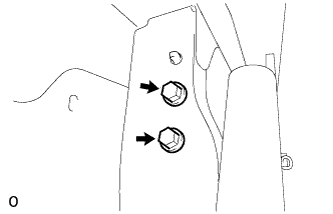
INSTALL TILT CAB MOUNTING LOCK ASSEMBLY RH
-
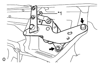
Text in Illustration *1 Guide Attach the guide and temporarily install the tilt cab mounting lock assembly RH with the 2 bolts.
-
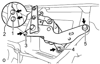
Temporarily install the other 3 bolts, and then tighten the 5 bolts in the order shown in the illustration.
- Torque:
- 20 N*m { 204 kgf*cm, 15 ft.*lbf }
-
-
INSTALL TILT CAB MOUNTING LOCK ASSEMBLY LH
-
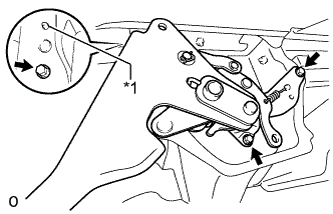
Text in Illustration *1 Guide Attach the guide and temporarily install the tilt cab mounting lock assembly LH with the 3 bolts.
-
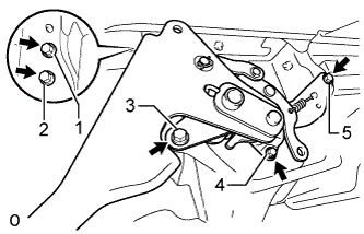
Temporarily install the other 2 bolts, and then tighten the 5 bolts in the order shown in the illustration.
- Torque:
- 20 N*m { 204 kgf*cm, 15 ft.*lbf }
-
Remove the 2 bolts.
-
-
INSTALL CAB MOUNTING SAFETY LATCH ASSEMBLY
-
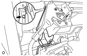
Temporarily install the cab mounting safety latch assembly with the bolt.
-
Temporarily install the other bolt, and then tighten the 2 bolts in the order shown in the illustration.
- Torque:
- 20 N*m { 204 kgf*cm, 15 ft.*lbf }
-
-
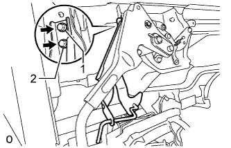
INSTALL TILT CAB LOCK SUPPORT
-
Attach the 2 claws to install the tilt cab lock support.
-
-
INSTALL TILT CAB LOCK HANDLE ROD
-
Text in Illustration *1 Tilt Cab Lock Support *2 Tilt Cab Lock Bracket Sub-Assembly (Cab Mounting Safety Latch Assembly) *3 Tilt Cab Lock Handle Rod Pass the tilt cab lock handle rod through the tilt cab lock bracket sub-assembly.
-
Rotate the tilt cab lock support as shown in the illustration, and attach the claw to install the tilt cab lock handle rod.
-
-
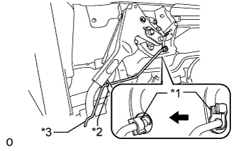
INSTALL TILT CAB LOCK CONNECTING PIPE SUB-ASSEMBLY
-

Text in Illustration *1 Clip *2 Plate Washer Install the tilt cab lock connecting pipe sub-assembly with the clip and plate washer.
-
Temporarily install the nut.
-
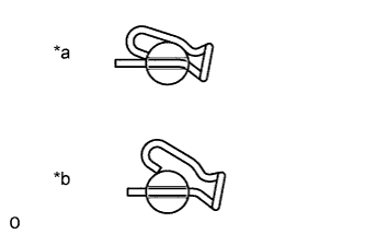
Text in Illustration *a CORRECT *b INCORRECT Check the installation of the clip.
-
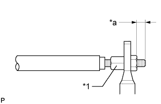
Text in Illustration *1 Adjusting Nut *a 11 mm (0.433 in.) Turn the adjusting nut and adjust the amount that the bolt protrudes.
Tech Tips
After installing the tilt cab lock connecting pipe sub-assembly, check that the cab mounting lock cannot be locked with the handle. If the cab mounting lock can be locked, turn the adjusting nut so that the amount that the bolt protrudes becomes smaller.
Standard 11 mm (0.433 in.) -
Tighten the nut.
- Torque:
- 18 N*m { 184 kgf*cm, 13 ft.*lbf }
-
-
TILT DOWN CAB