CAB MOUNTING CUSHION INSTALLATION

-
INSTALL NO. 2 CAB MOUNTING CUSHION SUB-ASSEMBLY
Tech Tips
Use the same procedure for both No. 2 cab mounting cushion sub-assemblies.
-
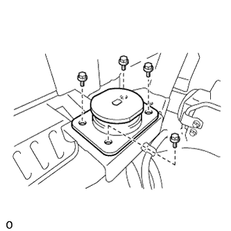
Install the No. 2 cab mounting cushion sub-assembly with the 4 bolts.
- Torque:
- 76 N*m { 775 kgf*cm, 56 ft.*lbf }
-
-
INSTALL NO. 2 CAB MOUNTING HOOK BRACKET SUB-ASSEMBLY
-
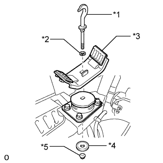
Text in Illustration *1 Cab Rear Mounting Hook *2 Plate Washer *3 No. 2 Cab Mounting Hook Bracket Sub-assembly *4 Cab Rear Mounting Rebound Stopper *5 Nut Install the cab rear mounting hook, plate washers, No. 2 cab mounting hook bracket sub-assembly and cab rear mounting rebound stopper with the nut.
Note
Install the same amount of plate washers that were removed.
-
Tighten the nut.
- Torque:
- 83 N*m { 846 kgf*cm, 61 ft.*lbf }
-
-
INSTALL NO. 1 CAB MOUNTING HOOK BRACKET SUB-ASSEMBLY
-
Install the cab rear mounting hook, plate washers, No. 1 cab mounting hook bracket sub-assembly and cab rear mounting rebound stopper with the nut.
Note
Install the same amount of plate washers that were removed.
-
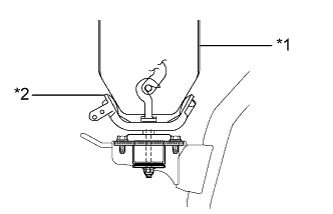
Text in Illustration *1 Cab *2 No. 1 Cab Mounting Hook Bracket Sub-assembly Tilt down the cab without locking it, and make sure that the cab and No. 1 cab mounting hook bracket sub-assemblies are uniformly contacting each other.
-
Tighten the nut.
- Torque:
- 83 N*m { 846 kgf*cm, 61 ft.*lbf }
-
Tilt up the cab Click here.
-
-
INSTALL AIR HOSE ASSEMBLY
-
Install 2 new hose clamps to the air hose assembly.
-
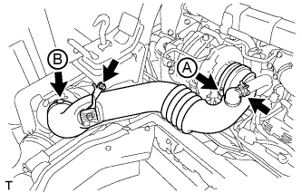
Install the air hose assembly with the bolt.
- Torque:
- 20 N*m { 199 kgf*cm, 14 ft.*lbf }
-
Tighten the 2 hose clamps.
- Torque:
- for hose clamp A
- 6.3 N*m { 64 kgf*cm, 56 in.*lbf }
- for hose clamp B
- 3.7 N*m { 38 kgf*cm, 33 in.*lbf }
-
Install the ventilation hose to the air hose assembly, and slide the clamp to secure the hose.
-
-
INSTALL FENDER SIDE APRON SUB-ASSEMBLY RH
-
Install the fender side apron sub-assembly RH with the 6 bolts.
- Torque:
- 12 N*m { 122 kgf*cm, 9 ft.*lbf }
-
-
INSTALL TILT CAB CONTROL SWITCH
-
Install the tilt cab control switch with the 2 nuts.
- Torque:
- 5.0 N*m { 51 kgf*cm, 44 in.*lbf }
-
Connect the connector and attach the clamp.
-
-
TILT DOWN CAB