FRONT DOOR REASSEMBLY

Tech Tips
-
Use the same procedure for the RH and LH sides.
-
The procedure listed below is for the LH side.
-
A bolt without a torque specification is shown in the standard bolt chart Click here.
-
INSTALL FRONT DOOR GLASS WEATHERSTRIP OUTER LH
-
Attach the 6 claws to install the front door outer glass weatherstrip LH.
-
-
INSTALL FRONT DOOR FRONT LOWER FRAME COVER UPPER LH
-
Attach the 3 clips to install a new front door front lower frame upper cover LH.
-
-
INSTALL FRONT FENDER TO COWL SIDE SEAL LH
-
Clean the front fender to cowl side seal LH installation surface.
-
Remove any double-sided tape remaining on the front fender to cowl side seal LH installation surface.
-
Clean the front fender to cowl side seal LH installation surface with non-residue solvent.
-
-
Using a heat light, heat the vehicle body surface and a new front fender to cowl side seal LH.
Note
Be careful to avoid burns that may be caused by the heat from the heat light or vehicle body.
Tech Tips
-
Vehicle body: 40 to 60°C
-
Front fender to cowl side seal LH surface: 20 to 30°C
-
-
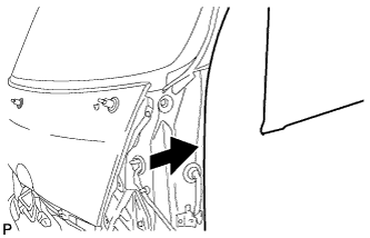
Push the front fender to cowl side seal LH in the direction shown in the illustration to install it.
-
Install the 2 clips.
-
-
INSTALL FRONT NO. 2 SIDE PANEL PROTECTOR LH
-
Install the front No. 2 side panel protector LH with the 2 bolts.
-
-
INSTALL FRONT SIDE PANEL LH
-
INSTALL FRONT DOOR TRIM COVER SUB-ASSEMBLY LH
-
Attach the 3 clips to install the front door trim cover sub-assembly LH.
-
Install the 5 clips.
-
-
INSTALL FRONT DOOR WEATHERSTRIP LH
-
Attach the 41 clips to install the front door weatherstrip LH.
-
-
INSTALL FRONT DOOR CHECK ARM BRACKET
-
Install the front door check arm bracket with the 2 bolts.
- Torque:
- 5.0 N*m { 51 kgf*cm, 44 in.*lbf }
-
-
INSTALL FRONT DOOR CHECK ASSEMBLY
-
Apply MP grease to the sliding parts of the front door check assembly.
-
Install the front door check assembly with the 2 bolts.
- Torque:
- 5.0 N*m { 51 kgf*cm, 44 in.*lbf }
-
-
INSTALL FRONT DOOR CHECK PIN
-
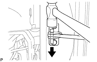
Using a hammer, install the front door check pin.
-
-
INSTALL DOOR LOCK CYLINDER LH
-
Install the door lock cylinder LH with the spring.
-
-
INSTALL FRONT DOOR OUTSIDE HANDLE ASSEMBLY LH
-
Install the front door outside handle assembly LH with the 2 bolts.
- Torque:
- 5.0 N*m { 51 kgf*cm, 44 in.*lbf }
-
Install a new seal to the service hole.
-
-
INSTALL FRONT DOOR LOCK ASSEMBLY RH (w/ Power Door Lock)
-
Apply MP grease to the sliding parts of the front door lock assembly RH.
-
Using a T30 "TORX" wrench, install the front door lock assembly RH with the 3 screws.
- Torque:
- 5.0 N*m { 51 kgf*cm, 44 in.*lbf }
-
Install the bolt.
- Torque:
- 5.0 N*m { 51 kgf*cm, 44 in.*lbf }
-
Connect the connector.
-
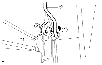
Text in Illustration *1 Door Outside Handle Snap *2 Front Door Lock Rod Sub-assembly RH Install the front door lock rod sub-assembly LH and attach the door outside handle snap.
-
Text in Illustration *1 Door Lock Control Link Snap *2 Front Door Outside Locking Link RH Install the front door outside locking link RH and attach the door lock control link snap.
-
-
INSTALL FRONT DOOR LOCK ASSEMBLY LH (w/o Power Door Lock)
-
Apply MP grease to the sliding parts of the front door lock assembly LH.
-
Using a T30 "TORX" wrench, install the front door lock assembly LH with the 3 screws.
- Torque:
- 5.0 N*m { 51 kgf*cm, 44 in.*lbf }
-
Install the bolt.
- Torque:
- 5.0 N*m { 51 kgf*cm, 44 in.*lbf }
-
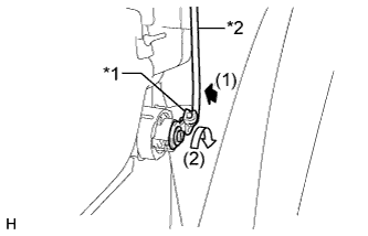
Text in Illustration *1 Front Door Lock Rod Sub-assembly LH *2 Door Lock Outside Handle Snap Attach the door outside handle snap to install the front door lock rod sub-assembly LH.
-
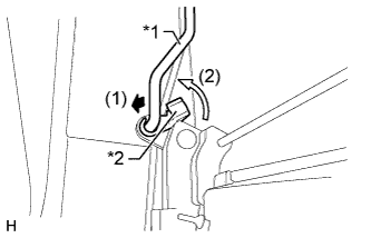
Text in Illustration *1 Front Door Outside Locking Link LH *2 Door Control Link Snap Attach the door lock control link snap to install the front door outside locking link LH.
-
-
INSTALL FRONT DOOR LOCK REMOTE CONTROL LINK LH
-
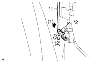
Text in Illustration *1 Front Door Lock Locking Snap *2 Front Door Lock Remote Control Link LH Attach the front door lock locking snap to install the front door lock remote control link LH.
-
Attach the front door lock link clamps to install the front door lock remote control link LH.
-
-
INSTALL FRONT DOOR LOCK CONTROL KNOB
-
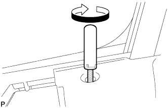
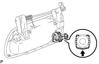
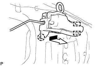
Turn the front door lock control knob in the direction indicated by the arrow in the illustration to install it to the front door lock assembly LH.
-
-
INSTALL FRONT DOOR REAR LOWER FRAME SUB-ASSEMBLY LH
-
Install the front door rear lower frame sub-assembly LH with the 2 bolts.
-
-
INSTALL FRONT DOOR GLASS RUN LH
-
Install the front door glass run LH.
-
-
INSTALL FRONT DOOR WINDOW REGULATOR SUB-ASSEMBLY LH
-
w/ Power Window:
-
Apply MP grease to the sliding and rotating areas of the front door window regulator sub-assembly LH.
-
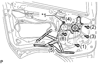
Text in Illustration *1 Temporary Bolt Install the temporary bolt to the front door window regulator sub-assembly LH.
-
Temporarily install the front door window regulator sub-assembly LH with the temporary bolt.
-
Temporarily install the 5 bolts, and then tighten the temporary bolt and 5 bolts.
- Torque:
- 5.0 N*m { 51 kgf*cm, 44 in.*lbf }
Tech Tips
Tighten the bolts in the order shown in the illustration.
-
Connect the connector.
-
-
w/o Power Window:
-
Apply MP grease to the sliding parts of the front door window regulator sub-assembly LH.
Note
Do not apply grease to the spring of the front door window regulator sub-assembly LH.
-
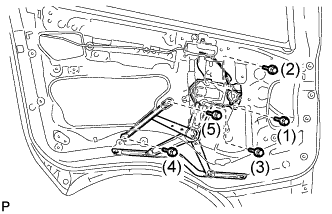
Install the front door window regulator sub-assembly LH with the 5 bolts in the order shown in the illustration.
- Torque:
- 5.0 N*m { 51 kgf*cm, 44 in.*lbf }
-
-
-
INSTALL FRONT DOOR GLASS SUB-ASSEMBLY LH
-
w/ Power Window:
-
Temporarily install the power window regulator master switch assembly with front door armrest base panel.
-
Connect the cable to the negative (-) battery terminal.
-
Move the front door window regulator sub-assembly LH so that the front door glass sub-assembly LH can be installed.
-
Disconnect the cable from the negative (-) battery terminal.
-
Remove the power window regulator master switch assembly with front door armrest base panel.
-
-
w/o Power Window:
-
Temporarily install the front door window regulator handle assembly.
-
Move the front door glass sub-assembly LH so that the front door glass bolts can be seen.
-
-
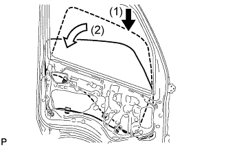
Insert the front door glass sub-assembly LH into the front door panel along the front door glass run LH as indicated by the arrows in the order shown in the illustration.
Note
Be careful not to damage the front door glass sub-assembly LH and front door glass run LH.
-
Install the front door glass sub-assembly LH with the 2 bolts.
- Torque:
- 5.0 N*m { 51 kgf*cm, 44 in.*lbf }
-
-
INSTALL FRONT DOOR SERVICE HOLE COVER LH
-
Apply new butyl tape to the front door panel.
-
Pass the link and wire harness through a new front door service hole cover LH.
-
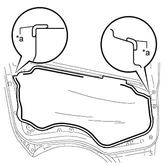
Text in Illustration *a Reference Point Attach the front door service hole cover LH using the reference points on the front door panel.
Note
-
Securely install the front door service hole cover LH to prevent wrinkles and air bubbles.
-
There should be no wrinkles or folds after installing the front door service hole cover LH.
-
After installing the front door service hole cover LH, check the seal quality.
-
-
-
INSTALL FRONT DOOR INSIDE HANDLE SUB-ASSEMBLY LH
-
Connect the front door lock remote control link LH to the front door inside handle sub-assembly LH.
-
Slide the front door inside handle sub-assembly LH as shown in the illustration and attach the 2 guides.
-
Attach the claw to install the front door inside handle sub-assembly LH.
-
Attach the clamp.
-
-
INSTALL FRONT DOOR INNER GLASS WEATHERSTRIP LH
-
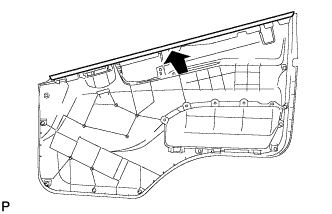
Slide the front door inner glass weatherstrip LH in the direction indicated by the arrow in the illustration to install it to the front door trim board sub-assembly LH.
-
-
INSTALL FRONT DOOR TRIM BOARD SUB-ASSEMBLY LH
-
Attach the 8 clips to install the front door trim board sub-assembly LH.
-
Install the clip.
-
-
INSTALL FRONT ASH RECEPTACLE ASSEMBLY
-
Install the front ash receptacle assembly.
-
-
INSTALL DOOR ASSIST GRIP ASSEMBLY LH
-
Install the door assist grip assembly LH with the 4 bolts.
- Torque:
- 19 N*m { 189 kgf*cm, 14 ft.*lbf }
-
-
INSTALL DOOR ASSIST GRIP COVER LH
-
Attach the 4 claws to install the door assist grip cover LH.
-
-
INSTALL FRONT DOOR INSIDE HANDLE BEZEL LH
-
Attach the 4 claws to install the front door inside handle bezel LH.
-
Install the screw.
-
-
INSTALL POWER WINDOW REGULATOR MASTER SWITCH ASSEMBLY WITH FRONT DOOR ARMREST BASE PANEL (w/ Power Window)
-
Connect the connector.
-
Attach the guide, 2 claws and clip to install the power window regulator master switch assembly with front door armrest base panel.
-
-
INSTALL FRONT UPPER ARMREST BASE PANEL LH (w/o Power Window)
-
Attach the guide and clip to install the front upper armrest base panel LH.
-
-
INSTALL FRONT DOOR WINDOW REGULATOR HANDLE ASSEMBLY (w/o Power Window)
-
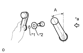
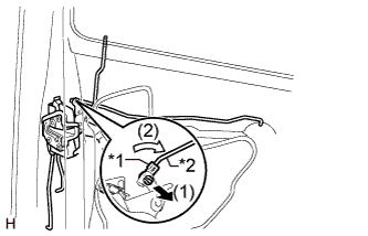
Text in Illustration *1 Snap Ring *2 Front Door Regulator Inside Handle Plate *a Front Side Temporarily install the front door window regulator handle assembly, fully close the window, and then remove the front door window regulator handle assembly.
-
Install the front door regulator inside handle plate and snap ring to the front door window regulator handle assembly.
-
Install the front door window regulator handle assembly to the front door window regulator sub-assembly LH as shown in the illustration.
Standard Angle Specified Condition A 15 to 45°
-
-
CONNECT CABLE TO NEGATIVE BATTERY TERMINAL (w/ Power Window)
Note
When disconnecting the cable, some systems need to be initialized after the cable is reconnected Click here.