POWER TAKE-OFF SYSTEM Power Take-off does not Operate
DESCRIPTION
Refer to "Power take-off cannot be sustained" Click here.
WIRING DIAGRAM
Refer to "Power take-off cannot be sustained" Click here.
INSPECTION PROCEDURE
Note
Inspect the fuses for circuits related to this system before performing the following inspection procedure.
PROCEDURE
-
CHECK CONTROL UNIT RELAY ASSEMBLY (POWER SOURCE CIRCUIT)
-
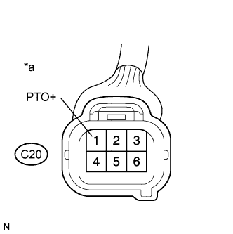
Text in Illustration *a Front view of wire harness connector
(to Control Unit Relay Assembly)
Disconnect the C20 control unit relay assembly connector.
-
Measure the voltage according to the value(s) in the table below.
Standard Voltage Tester Connection Condition Specified Condition C20-1 (PTO+) - Body ground
-
Ignition switch ON
-
Power take-off indicator switch ON
-
Power take-off clutch switch ON
20 to 28 V -
-
Reconnect the C20 control unit relay assembly connector.
NG 
CHECK HARNESS AND CONNECTOR (GROUND CIRCUIT) Click here
OK 
-
-
CHECK POWER TAKE-OFF ASSEMBLY (POWER SOURCE CIRCUIT)
-
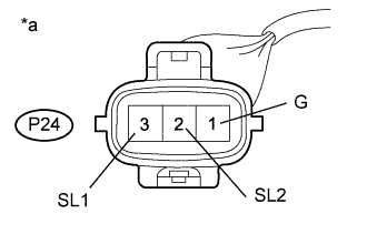
Text in Illustration *a Front view of wire harness connector
(to Power Take-off Assembly)
Disconnect the P24 power take-off assembly connector.
-
Measure the voltage according to the value(s) in the table below.
Standard Voltage Tester Connection Condition Specified Condition P24-1 (G) - P24-3 (SL1)
-
Ignition switch ON
-
Power take-off indicator switch ON
-
Power take-off clutch switch ON
-
Within 5 seconds after turning on power take-off indicator switch
20 to 28 V P24-1 (G) - P24-2 (SL2)
-
Ignition switch ON
-
Power take-off indicator switch ON
-
Power take-off clutch switch ON
20 to 28 V -
-
Reconnect the P24 power take-off assembly connector.
NG
CHECK HARNESS AND CONNECTOR (POWER TAKE-OFF ASSEMBLY - CONTROL UNIT RELAY ASSEMBLY AND BODY GROUND) Click here
OK 
REPLACE POWER TAKE-OFF ASSEMBLY Click here
-
-
CHECK HARNESS AND CONNECTOR (GROUND CIRCUIT)
-
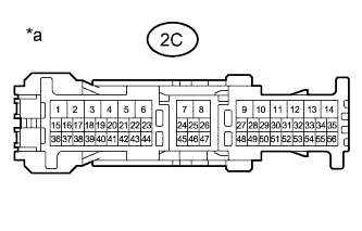
Text in Illustration *a Front view of wire harness connector
(to Instrument Panel Junction Block Assembly)
Disconnect the 2C instrument panel junction block assembly connector.
-
Measure the resistance according to the value(s) in the table below.
Standard Resistance Tester Connection Condition Specified Condition 2C-9 - Body ground Always Below 1 Ω -
Reconnect the 2C instrument panel junction block connector.
NG 
REPAIR OR REPLACE HARNESS OR CONNECTOR (GROUND CIRCUIT)
OK
-
-
CHECK INSTRUMENT PANEL JUNCTION BLOCK ASSEMBLY
-
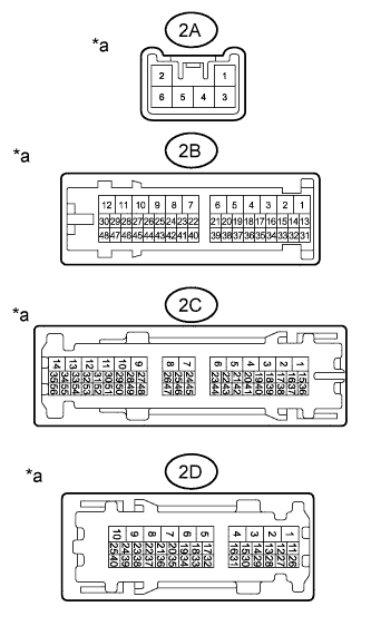
Text in Illustration *a Component with harness connected
(Instrument Panel Junction Block Assembly)
Remove the instrument panel junction block assembly with the connector(s) still connected.
-
Text in Illustration *a Front view of wire harness connector
(to Instrument Panel Junction Block Assembly)
Measure the voltage according to the value(s) in the table below.
Standard Voltage Tester Connection Condition Specified Condition 2B-26 - Body ground
-
Ignition switch ON
-
Power take-off indicator switch ON
-
Power take-off clutch switch ON
20 to 28 V 2C-7 - Body ground
-
Ignition switch ON
-
Power take-off indicator switch ON
-
Power take-off clutch switch ON
20 to 28 V 2D-31 - Body ground
-
Ignition switch ON
-
Power take-off indicator switch OFF
-
Power take-off clutch switch OFF
20 to 28 V 2A-3 - Body ground Always 20 to 28 V -
-
Disconnect the 2C instrument panel junction block assembly connector.
-
Measure the resistance according to the value(s) in the table below.
Standard Resistance Tester Connection Condition Specified Condition 2C-7 - 2C-9 Always 2.6 to 2.8 kΩ Result Result Proceed to NG (2C-7 and 2B-26) A NG (2B-26) B NG (2C-7 - 2C-9) NG (2D-31) NG (2A-3 - 2D-31 or 2B-26) C OK D
B
REPLACE INSTRUMENT PANEL JUNCTION BLOCK ASSEMBLY
C
REPAIR OR REPLACE HARNESS OR CONNECTOR (BATTERY - INSTRUMENT PANEL JUNCTION BLOCK ASSEMBLY)
D
REPAIR OR REPLACE HARNESS OR CONNECTOR (INSTRUMENT PANEL JUNCTION BLOCK ASSEMBLY - CONTROL UNIT RELAY ASSEMBLY)
A
-
-
CHECK HARNESS AND CONNECTOR (INSTRUMENT PANEL JUNCTION BLOCK ASSEMBLY - POWER TAKE-OFF INDICATOR SWITCH ASSEMBLY)
-
Disconnect the P32 power take-off indicator switch assembly connector.
-
Disconnect the 2C instrument panel junction block assembly connector.
-
Measure the resistance according to the value(s) in the table below.
Standard Resistance Tester Connection Condition Specified Condition 2C-7 - P32-2 (-) Always Below 1 Ω 2C-7 or P32-2 (-) - Body ground Always 10 kΩ or higher
NG
REPAIR OR REPLACE HARNESS OR CONNECTOR (POWER TAKE-OFF INDICATOR SWITCH - INSTRUMENT PANEL JUNCTION BLOCK ASSEMBLY)
OK
-
-
INSPECT POWER TAKE-OFF INDICATOR SWITCH ASSEMBLY
-
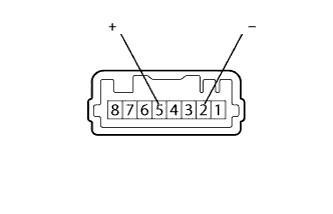
Remove the power take-off indicator switch assembly Click here.
-
Measure the resistance according to the value(s) in the table below.
Standard Resistance Tester Connection Condition Specified Condition 2 (-) - 5 (+) Not Pushed 10 kΩ or higher 2 (-) - 5 (+) Pushed in Below 1 Ω
NG
REPLACE POWER TAKE-OFF INDICATOR SWITCH ASSEMBLY Click here
OK
-
-
CHECK HARNESS AND CONNECTOR (POWER TAKE-OFF INDICATOR SWITCH ASSEMBLY - POWER TAKE-OFF CLUTCH SWITCH)
-
Disconnect the E45 power take-off clutch switch assembly connector.
-
Disconnect the P32 power take-off indicator switch assembly connector.
-
Measure the resistance according to the value(s) in the table below.
Standard Resistance Tester Connection Condition Specified Condition E45-2 (PTC-) - P32-5 (+) Always Below 1 Ω E45-2 (PTC-) or P32-5 (+) - Body ground Always 10 kΩ or higher
NG
REPAIR OR REPLACE HARNESS OR CONNECTOR (POWER TAKE-OFF INDICATOR SWITCH - POWER TAKE-OFF CLUTCH SWITCH)
OK
-
-
INSPECT POWER TAKE-OFF CLUTCH SWITCH
-
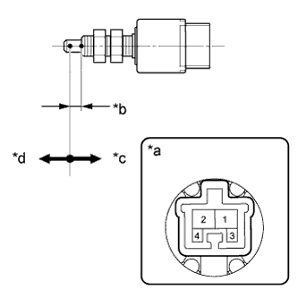
Text in Illustration *a Component without harness connected
(Power Take-Off Clutch Switch Assembly)
*b 4.75 to 6.25 mm (0.19 to 0.25 in.) *c On *d Off Remove the power take-off clutch switch assembly.
-
Measure the resistance according to the value(s) in the table below.
Standard Resistance Tester Connection Switch Condition Specified Condition 1 - 2 On Below 1 Ω 1 - 2 Off 10 kΩ or higher
NG
REPLACE POWER TAKE-OFF CLUTCH SWITCH ASSEMBLY Click here
OK
-
-
CHECK HARNESS AND CONNECTOR (INSTRUMENT PANEL JUNCTION BLOCK ASSEMBLY - POWER TAKE-OFF CLUTCH SWITCH)
-
Disconnect the 2D instrument panel junction block assembly connector.
-
Measure the resistance according to the value(s) in the table below.
Standard Resistance Tester Connection Condition Specified Condition 2D-31 - E45-1 (PTC+) Always Below 1 Ω 2D-31 or E45-1 (PTC+) - Body ground Always 10 kΩ or higher
NG
REPAIR OR REPLACE HARNESS AND CONNECTOR (INSTRUMENT PANEL JUNCTION BLOCK ASSEMBLY - POWER TAKE-OFF CLUTCH SWITCH)
OK
REPLACE INSTRUMENT PANEL JUNCTION BLOCK ASSEMBLY
-
-
CHECK HARNESS AND CONNECTOR (POWER TAKE-OFF ASSEMBLY - CONTROL UNIT RELAY ASSEMBLY AND BODY GROUND)
-
Disconnect the P24 power take-off assembly connector.
-
Disconnect the C20 control unit relay assembly connector.
-
Measure the resistance according to the value(s) in the table below.
Standard Resistance Tester Connection Condition Specified Condition P24-3 (SL1) - C20-4 (SLP) Always Below 1 Ω P24-2 (SL2) - C20-5 (SLH) Always Below 1 Ω P24-1 (G) - C20-3 (SL-) Always Below 1 Ω P24-3 (SL1) - Body ground Always 10 kΩ or higher P24-2 (SL2) - Body ground Always 10 kΩ or higher P24-1 (G) - Body ground Always 10 kΩ or higher C20-6 (PTO-) - Body ground Always Below 1 Ω
NG
REPAIR OR REPLACE HARNESS OR CONNECTOR (CONTROL UNIT RELAY ASSEMBLY - POWER TAKE-OFF ASSEMBLY OR GROUND)
OK
REPLACE CONTROL UNIT RELAY ASSEMBLY Click here
-