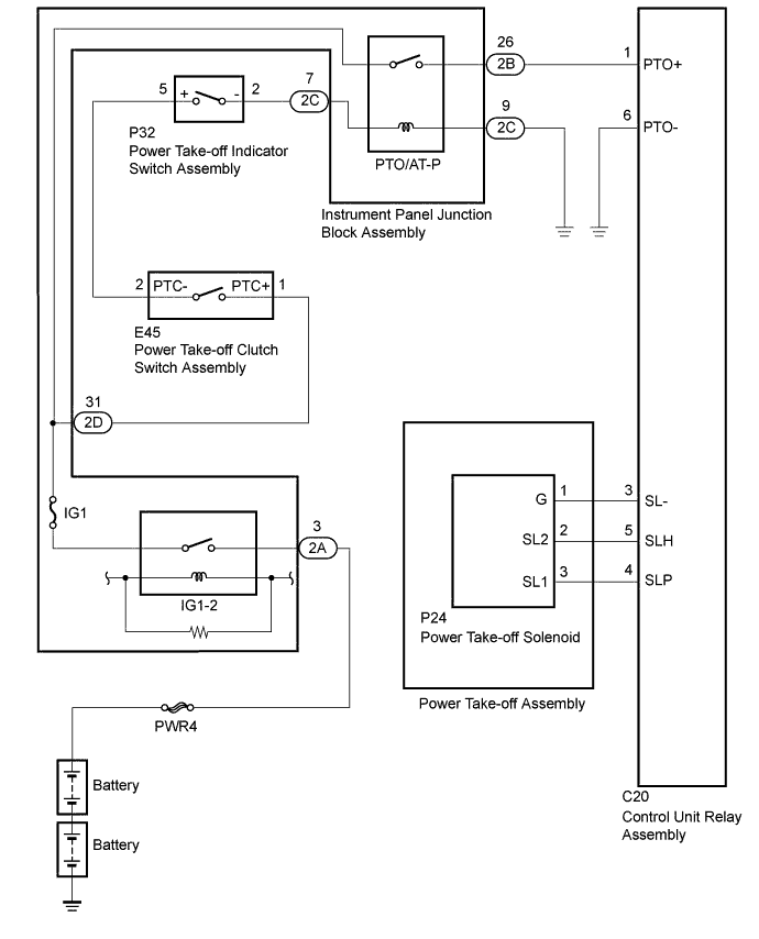
POWER TAKE-OFF SYSTEM Power Take-off cannot be Sustained
DESCRIPTION
The control unit relay assembly applies power take-off activation voltage to terminals SLP and SLH when the unit receives an input signal from the power take-off indicator switch.
After the activation voltage is applied, the power take-off assembly begins operation.
Signals from terminal SLP will stop being output approximately 5 seconds after the control unit relay assembly begins operation (voltage input to terminal SL1 of the power take-off assembly is 0 V). At this time, only voltage output from terminal SLH is present, which sustains the power take-off operation.
Turning the power take-off indicator switch off will stop the output from terminal SLH (voltage input to terminal SL2 of the power take-off assembly is 0 V), and the power take-off returns to the original position due to the return spring.
WIRING DIAGRAM
INSPECTION PROCEDURE
Note
Inspect the fuses for circuits related to this system before performing the following inspection procedure.
PROCEDURE
-
INSPECT POWER TAKE-OFF ASSEMBLY
-
Disconnect the P24 power take-off assembly connector.
-
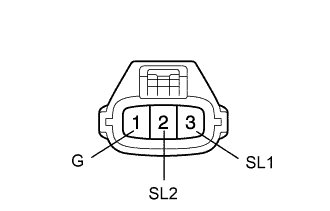
Measure the resistance according to the value(s) in the table below.
Standard Resistance Tester Connection Condition Specified Condition 2 (SL2) - 1 (G) Coil temperature at 20°C (68°F) 35 Ω 3 (SL1) - 1 (G) Coil temperature at 20°C (68°F) 2.9 Ω -
Reconnect the P24 power take-off assembly connector.
NG 
REPLACE POWER TAKE-OFF ASSEMBLY Click here
OK 
-
-
CHECK CONTROL UNIT RELAY ASSEMBLY (OUTPUT VOLTAGE)
-
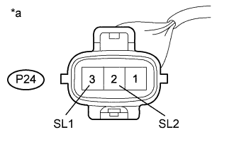
Text in Illustration *a Front view of wire harness connector
(to Power Take-off Assembly)
Disconnect the P24 power take-off assembly connector.
-
Measure the voltage according to the value(s) in the table below.
Standard Voltage Tester Connection Condition Specified Condition P24-3 (SL1) - Body ground
-
Ignition switch ON
-
Power take-off indicator switch ON
-
Power take-off clutch switch ON
-
Within 5 seconds after turning on power take-off indicator switch
20 to 28 V P24-2 (SL2) - Body ground
-
Ignition switch ON
-
Power take-off indicator switch ON
-
Power take-off clutch switch ON
20 to 28 V -
-
Reconnect the P24 power take-off assembly connector.
NG 
CHECK HARNESS AND CONNECTOR (POWER TAKE-OFF ASSEMBLY - CONTROL UNIT RELAY ASSEMBLY) Click here
OK 
PROCEED TO NEXT CIRCUIT INSPECTION SHOWN IN PROBLEM SYMPTOMS TABLE Click here
-
-
CHECK HARNESS AND CONNECTOR (POWER TAKE-OFF ASSEMBLY - CONTROL UNIT RELAY ASSEMBLY)
-
Disconnect the P24 power take-off assembly connector.
-
Disconnect the C20 control unit relay assembly connector.
-
Measure the resistance according to the value(s) in the table below.
Standard Resistance Tester Connection Condition Specified Condition P24-1 (G) - C20-3 (SL-) Always Below 1 Ω P24-2 (SL2) - C20-5 (SLH) Always Below 1 Ω P24-3 (SL1) - C20-4 (SLP) Always Below 1 Ω P24-1 (G) - Body ground Always 10 kΩ or higher P24-2 (SL2) - Body ground Always 10 kΩ or higher P24-3 (SL1) - Body ground Always 10 kΩ or higher -
Reconnect the P24 power take-off assembly connector and C20 control unit relay assembly connector.
NG
REPAIR OR REPLACE HARNESS OR CONNECTOR (POWER TAKE-OFF ASSEMBLY - CONTROL UNIT RELAY ASSEMBLY)
OK
-
-
CHECK CONTROL UNIT RELAY ASSEMBLY (POWER SOURCE CIRCUIT)
Text in Illustration *a Front view of wire harness connector
(to Control Unit Relay Assembly)
-
Disconnect the C20 control unit relay assembly connector.
-
Measure the voltage according to the value(s) in the table below.
Standard Voltage Tester Connection Condition Specified Condition C20-1 (PTO+) - C20-6 (PTO-)
-
Ignition switch ON
-
Power take-off indicator switch ON
-
Power take-off clutch switch ON
20 to 28 V -
NG
CHECK HARNESS AND CONNECTOR (INSTRUMENT PANEL JUNCTION BLOCK ASSEMBLY - CONTROL UNIT RELAY ASSEMBLY) Click here
OK
REPLACE CONTROL UNIT RELAY ASSEMBLY Click here
-
-
CHECK HARNESS AND CONNECTOR (INSTRUMENT PANEL JUNCTION BLOCK ASSEMBLY - CONTROL UNIT RELAY ASSEMBLY)
-
Disconnect the 2B instrument panel junction block assembly connector.
-
Disconnect the C20 control relay assembly connector.
-
Measure the resistance according to the value(s) in the table below.
Standard Resistance Tester Connection Condition Specified Condition 2B-26 - C20-1 (PTO+) Always Below 1 Ω
NG
REPAIR OR REPLACE HARNESS OR CONNECTOR (INSTRUMENT PANEL JUNCTION BLOCK ASSEMBLY - CONTROL UNIT RELAY ASSEMBLY)
OK
-
-
CHECK INSTRUMENT PANEL JUNCTION BLOCK ASSEMBLY
-
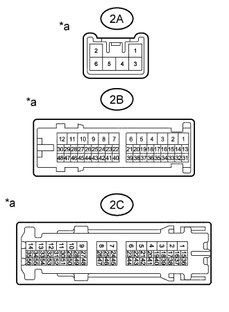
Text in Illustration *a Component with harness connected
(Instrument Panel Junction Block Assembly)
Remove the instrument panel junction block assembly with the connector(s) still connected.
-
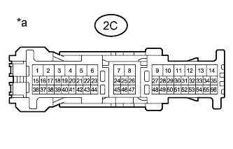
Text in Illustration *a Front view of wire harness connector
(to Instrument Panel Junction Block Assembly)
Measure the voltage according to the value(s) in the table below.
Standard Voltage Tester Connection Condition Specified Condition 2A-3 - 2B-26
-
Ignition switch ON
-
Power take-off indicator switch ON
-
Power take-off clutch switch ON
0 V 2A-3 - 2C-9
-
Ignition switch ON
-
Power take-off indicator switch ON
-
Power take-off clutch switch ON
20 to 28 V 2A-3 - Body ground Always 20 to 28 V -
-
Disconnect the 2C instrument panel junction block assembly connector.
-
Measure the resistance according to the value(s) in the table below.
Standard Resistance Tester Connection Condition Specified Condition 2C-7 - 2C-9 Always 2.6 to 2.8 kΩ Result Result Proceed to OK A OK (2A-3 - Body ground)
NG (2A-3 - 2B-26 or 2C-9)
B NG (2A-3 - Body ground) C
B
REPLACE INSTRUMENT PANEL JUNCTION BLOCK ASSEMBLY
C
REPAIR OR REPLACE HARNESS OR CONNECTOR (BATTERY - INSTRUMENT PANEL JUNCTION BLOCK ASSEMBLY)
A
PROCEED TO NEXT CIRCUIT INSPECTION SHOWN IN PROBLEM SYMPTOMS TABLE Click here
-