POWER TAKE-OFF SYSTEM Power Take-off does not Return to the Original Position
DESCRIPTION
Refer to "Power take-off cannot be sustained" Click here.
WIRING DIAGRAM
Refer to "Power take-off cannot be sustained" Click here.
INSPECTION PROCEDURE
Note
Inspect the fuses for circuits related to this system before performing the following inspection procedure.
PROCEDURE
-
CHECK CONTROL UNIT RELAY ASSEMBLY (OUTPUT VOLTAGE)
-
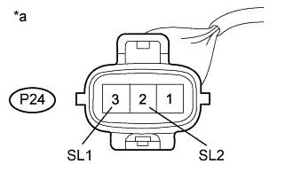
Text in Illustration *a Front view of wire harness connector
(to Power Take-off Assembly)
Disconnect the P24 power take-off assembly connector.
-
Measure the voltage according to the value(s) in the table below.
Standard Voltage Tester Connection Condition Specified Condition P24-2 (SL2) - Body ground
-
Ignition switch ON
-
Power take-off indicator switch ON
-
Power take-off clutch switch ON
20 to 28 V P24-3 (SL1) - Body ground
-
Ignition switch ON
-
Power take-off indicator switch ON
-
Power take-off clutch switch ON
-
Within 5 seconds after turning on power take-off indicator switch
20 to 28 V P24-3 (SL1) - Body ground
-
Ignition switch ON
-
Power take-off indicator switch ON
-
Power take-off clutch switch ON
-
5 seconds after turning on power take-off indicator switch
0 V P24-2 (SL2) - Body ground Power take-off indicator switch OFF 0 V P24-3 (SL1) - Body ground Power take-off indicator switch OFF 0 V -
-
Reconnect the P24 power take-off assembly connector.
NG 
CHECK CONTROL UNIT RELAY ASSEMBLY (INPUT VOLTAGE) Click here
OK 
REPLACE POWER TAKE-OFF ASSEMBLY Click here
-
-
CHECK CONTROL UNIT RELAY ASSEMBLY (INPUT VOLTAGE)
-
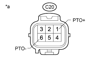
Text in Illustration *a Front view of wire harness connector
(to Control Unit Relay Assembly)
Disconnect the C20 control unit relay assembly connector.
-
Measure the voltage according to the value(s) in the table below.
Standard Voltage Tester Connection Switch Condition Specified Condition C20-1 (PTO+) - C20-6 (PTO-)
-
Ignition switch ON
-
Power take-off indicator switch ON
-
Power take-off clutch switch ON
20 to 28 V C20-1 (PTO+) - C20-6 (PTO-) Power take-off indicator switch OFF 0 V -
NG
INSPECT POWER TAKE-OFF INDICATOR SWITCH ASSEMBLY Click here
OK
REPLACE CONTROL UNIT RELAY ASSEMBLY Click here
-
-
INSPECT POWER TAKE-OFF INDICATOR SWITCH ASSEMBLY
-
Remove the power take-off indicator switch assembly Click here.
-
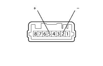
Measure the resistance according to the value(s) in the table below.
Standard Resistance Tester Connection Switch Condition Specified Condition 2 (-) - 5 (+) Not Pushed 10 kΩ or more 2 (-) - 5 (+) Pushed in Below 1 Ω -
Reinstall the power take-off indicator switch assembly Click here.
NG 
REPLACE POWER TAKE-OFF INDICATOR SWITCH ASSEMBLY Click here
OK 
-
-
CHECK HARNESS AND CONNECTOR
-
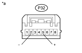
Text in Illustration *a Front view of wire harness connector
(to Power Take-off Indicator Switch Assembly)
Disconnect the P32 control unit relay assembly connector.
-
Measure the resistance according to the value(s) in the table below.
Standard Resistance Tester Connection Condition Specified Condition P32-2 (-) - P32-5 (+) Always 10 kΩ or higher
NG
REPAIR OR REPLACE HARNESS OR CONNECTOR
OK
PROCEED TO NEXT CIRCUIT INSPECTION SHOWN IN PROBLEM SYMPTOMS TABLE Click here
-