POWER TAKE-OFF SYSTEM TERMINALS OF ECU

-
TERMINALS OF COMPONENTS
-
Power take-off assembly
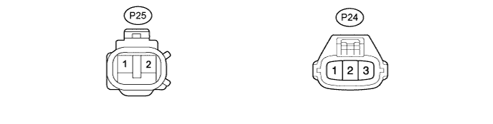
Terminal No.(Symbol) Terminal Description P24-1 (G) Power take-off assembly ground P24-2 (SL2) Power take-off assembly coil input (Sustain) P24-3 (SL1) Power take-off assembly coil input (Activation) P25-1 (E) Power take-off position switch P25-2 (B) Power take-off position switch -
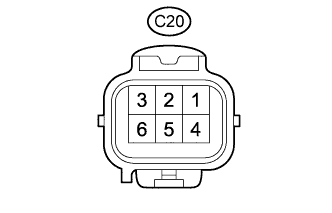
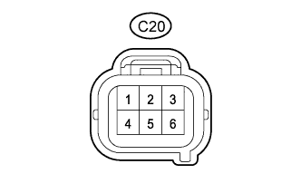
Control unit relay assembly
Terminal No.(Symbol) Terminal Description 1 (PTO+) Power source 3 (SL-) Power take-off assembly ground 4 (SLP) Power take-off assembly coil output (Activation) 5 (SLH) Power take-off assembly coil output (Sustain) 6 (PTO-) Ground
-
-
TERMINAL INSPECTION
-
Disconnect the power take-off assembly connector and measure the voltage or resistance on the wire harness side.
Tech Tips
-
Voltage/resistance cannot be measured with the connectors connected to the components (power take-off assembly, control unit relay assembly) as the connectors are watertight.
-
Control unit relay assembly outputs 20 to 28 V to the power take-off assembly for approximately 5 seconds when the power take-off indicator switch turned ON.

Terminal No.
(Symbol)
Wiring Color Terminal Description Condition Specified Condition P24-1 (G) - Body ground B - Body ground Power take-off assembly ground Always Below 1 Ω P24-2 (SL2) - Body ground Y - Body ground Power take-off assembly coil input
-
Ignition switch ON
-
Power take-off indicator switch ON
-
Power take-off clutch switch ON
20 to 28 V P24-2 (SL2) - Body ground Y - Body ground Power take-off assembly coil input Power take-off indicator switch OFF 0 V P24-3 (SL1) - Body ground P - Body ground Power take-off assembly coil input
-
Ignition switch ON
-
Power take-off indicator switch ON
-
Power take-off clutch switch ON
20 to 28 V P24-3 (SL1) - Body ground P - Body ground Power take-off assembly coil input
-
Ignition switch ON
-
Power take-off indicator switch ON
-
Power take-off clutch switch ON
(After 5 seconds)
20 to 28 V → 0 V P24-3 (SL1) - Body ground P - Body ground Power take-off assembly coil input Power take-off indicator switch OFF 0 V P25-1 (E) - P25-2 (B) R - G-R Power take-off position switch
-
Ignition switch ON
-
Power take-off indicator switch ON
-
Power take-off clutch switch ON
Below 1 Ω P25-1 (E) - P25-2 (B) R - G-R Power take-off position switch Power take-off indicator switch OFF 10 kΩ or higher -
-
Disconnect the control unit relay assembly connector and measure the voltage or resistance on the wire harness side.
Tech Tips
Voltage/resistance cannot be measured with the connectors connected to the components (power take-off assembly, control unit relay assembly) as the connectors are watertight.
Terminal No.
(Symbol)
Wiring Color Terminal Description Condition Specified Condition C20-1 (PTO+) - Body ground LG - Body ground Power source
-
Ignition switch ON
-
Power take-off indicator switch ON
-
Power take-off clutch switch ON
20 to 28 V C20-6 (PTO-) - Body ground W-B - Body ground Ground Always Below 1 Ω -
-