ROOF HEADLINING INSTALLATION

-
INSTALL ROOF HEADLINING ASSEMBLY
-
Place the roof headlining assembly into the vehicle through the passenger door.
Note
Be careful not to damage the roof headlining assembly when placing it in the cabin.
-
Install the roof headlining assembly with the 6 clips.
-
-
INSTALL ASSIST GRIP SUB-ASSEMBLY (w/ Assist Grip)
-
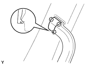
Install the assist grip sub-assembly with the 2 bolts.
- Torque:
- 3.5 N*m { 36 kgf*cm, 31 in.*lbf }
-
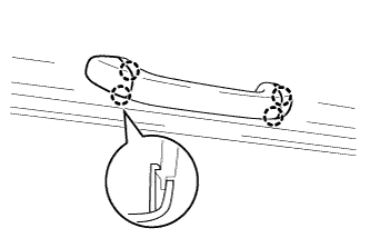
Attach the 4 claws to close the 2 covers.
-
-
INSTALL CLIP (w/o Assist Grip)
-
Install the 2 clips.
-
-
INSTALL COAT HOOK
Tech Tips
Use the same procedure for the other coat hook.
-
Attach the claw to install the coat hook.
-
Install the screw.
-
-
INSTALL NO. 2 ROOM LIGHT ASSEMBLY (w/ LED Type Room Light)
-
Connect the connector.
-
Install the No. 2 room light assembly with the screw.
-
-
INSTALL NO. 1 ROOM LIGHT COVER (w/ LED Type Room Light)
-
Attach the 2 claws and 2 guides to install the No. 1 room light cover.
-
-
INSTALL NO. 1 ROOM LIGHT ASSEMBLY
-
Connect the connector.
-
Install the No. 1 room light assembly with the 2 screws.
-
-
INSTALL NO. 1 ROOM LIGHT LENS
-
Attach the 2 claws and 2 guides to install the No. 1 room light lens.
-
-
INSTALL ROOF CONSOLE BOX
-
Attach the 2 guides and 2 claws to install the roof console box.
-
Install the 4 screws.
-
-
INSTALL VISOR HOLDER
Tech Tips
Use the same procedure for the other visor holder.
-
Attach the claw to install the visor holder.
-
Install the screw.
-
-
INSTALL VISOR ASSEMBLY RH
-
Install the visor assembly RH with the 2 screws.
-
-
INSTALL VISOR ASSEMBLY LH
Tech Tips
Use the same procedure described for the RH side.
-
INSTALL INNER REAR VIEW MIRROR ASSEMBLY
-
Install the inner rear view mirror assembly with the 2 screws.
- Torque:
- 2.2 N*m { 22 kgf*cm, 19 in.*lbf }
-
-
INSTALL FRONT DOOR OPENING TRIM RH
-
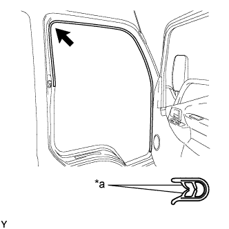
Text in Illustration *a Paint Mark (Blue) 
Mark Position Align the paint mark on the front door opening trim RH with the mark position on the vehicle and install the front door opening trim RH as shown in the illustration.
-
-
INSTALL FRONT DOOR OPENING TRIM LH
-
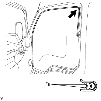
Text in Illustration *a Paint Mark (Pink) Mark Position Align the paint mark on the front door opening trim LH with the mark position on the vehicle and install the front door opening trim LH as shown in the illustration.
-
-
INSTALL FRONT PILLAR GARNISH RH
-
Attach the 2 clips to install the front pillar garnish RH.
-
-
INSTALL FRONT PILLAR GARNISH LH
Tech Tips
Use the same procedure described for the RH side.
-
INSTALL NO. 2 ASSIST GRIP ASSEMBLY RH
-
Install the No. 2 assist grip assembly RH with the 2 bolts.
- Torque:
- 14 N*m { 138 kgf*cm, 10 ft.*lbf }
-
-
INSTALL NO. 2 ASSIST GRIP ASSEMBLY LH
Tech Tips
Use the same procedure described for the RH side.
-
INSTALL ASSIST GRIP PLUG
Tech Tips
Use the same procedure for the other assist grip plug.
-
Attach the 3 claws to install the assist grip plug.
-
-
INSTALL FRONT QUARTER TRIM PANEL ASSEMBLY RH (for Full-trim)
-
Attach the 5 clips to install the front quarter trim panel assembly RH.
-
-
INSTALL FRONT QUARTER TRIM PANEL ASSEMBLY LH (for Full-trim)
Tech Tips
Use the same procedure described for the RH side.
-
INSTALL SEAT BELT ANCHOR COVER CAP (for Driver Side)
-
Attach the 4 claws to install the seat belt anchor cover cap.
-
-
INSTALL LOWER QUARTER TRIM PANEL ASSEMBLY RH
-
Attach the 3 claws to install the lower quarter trim panel assembly RH.
-
-
INSTALL LOWER QUARTER TRIM PANEL ASSEMBLY LH
Tech Tips
Use the same procedure described for the RH side.
-
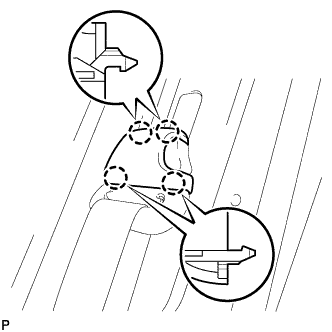
CONNECT FRONT SEAT OUTER BELT ASSEMBLY RH
-
Temporarily connect the front seat outer belt assembly RH floor anchor with the bolt.
-
Check that the front seat outer belt assembly RH is not twisted.
-
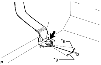
Text in Illustration *a 20° *b Vehicle Inside (0°) Tighten the bolt to connect the front seat outer belt assembly RH floor anchor.
- Torque:
- 42 N*m { 428 kgf*cm, 31 ft.*lbf }
Note
Install the front seat outer belt assembly RH so that the angle of the floor anchor is within the standard range.
Standard 0° to 20°
-
-
CONNECT FRONT SEAT OUTER BELT ASSEMBLY LH
Tech Tips
Use the same procedure described for the RH side.
-
INSTALL FRONT DOOR SCUFF PLATE RH
-
Install the front door scuff plate RH with the 4 screws.
-
-
INSTALL FRONT DOOR SCUFF PLATE LH
Tech Tips
Use the same procedure described for the RH side.