HEADLIGHT DIMMER SWITCH INSPECTION
PROCEDURE
-
INSPECT HEADLIGHT DIMMER SWITCH ASSEMBLY
-
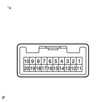
Text in Illustration *a Component without harness connected
(Headlight Dimmer Switch Assembly)
Measure the resistance according to the value(s) in the table below.
Standard Resistance Light Control Switch Tester Connection Switch Condition Specified Condition 12 (EL) - 18 (T) Light control switch off 10 kΩ or higher 18 (T) - 19 (A) Light control switch off 10 kΩ or higher 19 (A) - 20 (H) Light control switch off 10 kΩ or higher 12 (EL) - 18 (T) Light control switch in tail position Below 1 Ω 12 (EL) - 18 (T) Light control switch in head position Below 1 Ω 18 (T) - 20 (H) Light control switch in head position Below 1 Ω 12 (EL) - 19 (A) Light control switch in AUTO position Below 1 Ω Dimmer Switch Tester Connection Switch Condition Specified Condition 11 (HU) - 12 (EL) Dimmer switch in high position Below 1 Ω 12 (EL) - 11 (HU) Dimmer switch in high flasher position Below 1 Ω 12 (EL) - 17 (HF) Below 1 Ω Turn Signal Switch Tester Connection Switch Condition Specified Condition 12 (EL) - 13 (TR) Right turn Below 1 Ω 12 (EL) - 13 (TR) Neutral 10 kΩ or higher 12 (EL) - 15 (TL) Neutral 10 kΩ or higher 12 (EL) - 15 (TL) Left turn Below 1 Ω Front Fog Light Switch Tester Connection Switch Condition Specified Condition 3 (LFG) - 4 (BFG) Front fog light switch off 10 kΩ or higher 3 (LFG) - 4 (BFG) Front fog light switch on Below 1 Ω Rear Fog Light Switch Tester Connection Switch Condition Specified Condition 3 (LFG) - 4 (BFG) - 2(B) Rear fog light switch off 10 kΩ or higher 3 (LFG) - 4 (BFG) - 2(B) Rear fog light switch on Below 1 Ω If the result is not as specified, replace the headlight dimmer switch assembly.
-