LIGHTING SYSTEM Low Beam Headlight Circuit
DESCRIPTION
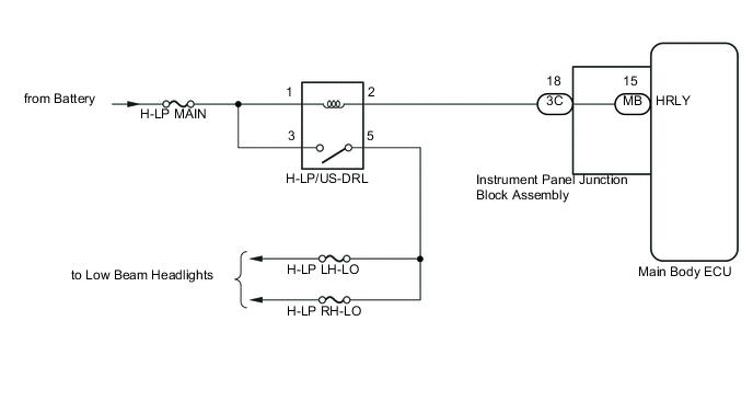
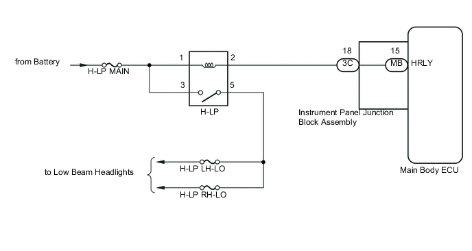
The main body ECU controls the low beam headlights via the H-LP/US-DRL relay.
WIRING DIAGRAM
-
except 2ZR-FE
-
for 2ZR-FE
CAUTION / NOTICE / HINT
Note
Inspect the fuses for circuits related to this system before performing the following inspection procedure.
PROCEDURE
-
PERFORM ACTIVE TEST USING GTS (HEADLIGHT RELAY)
-
Connect the GTS to the DLC3.
-
Turn the ignition switch to ON (IG).
-
Turn the GTS on.
-
Enter the following menus: Body Electrical / Main Body / Active Test.
-
According to the display on the GTS, perform the Active Test.
Main Body Tester Display Test Part Control Range Diagnostic Note Headlight Relay Headlight relay OFF or ON - OK Headlight relay operates (Low beam headlights illuminate).
OK 
PROCEED TO NEXT SUSPECTED AREA SHOWN IN PROBLEM SYMPTOMS TABLE Click here
NG 
-
-
INSPECT HEADLIGHT RELAY (H-LP/US-DRL RELAY OR H-LP RELAY)
-
except 2ZR-FE
-
Remove the headlight relay (H-LP/US-DRL relay).
-
Inspect the headlight relay (H-LP/US-DRL relay).
-
-
for 2ZR-FE
-
Remove the headlight relay (H-LP relay).
-
Inspect the headlight relay (H-LP relay).
-
NG
REPLACE HEADLIGHT RELAY (H-LP/US-DRL RELAY)
OK
-
-
CHECK HARNESS AND CONNECTOR (HEADLIGHT RELAY(H-LP/US-DRL) - BATTERY)
-
except 2ZR-FE
-
Remove the headlight relay (H-LP/US-DRL relay) from the No. 2 engine room relay block.
-
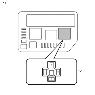
*1 No. 2 Engine Room Relay Block *2 Headlight Relay (H-LP/US-DRL Relay) Holder Measure the voltage according to the value(s) in the table below.
Standard Voltage Tester Connection Condition Specified Condition H-LP/US-DRL-1 - Body ground Always 11 to 14 V H-LP/US-DRL-3 - Body ground Always 11 to 14 V
-
-
for 2ZR-FE
-
Remove the headlight relay (H-LP relay) from the No. 2 engine room relay block.
-
*1 No. 2 Engine Room Relay Block *2 Headlight Relay (H-LP Relay) Holder Measure the voltage according to the value(s) in the table below.
Standard Voltage Tester Connection Condition Specified Condition H-LP-1 - Body ground Always 11 to 14 V H-LP-3 - Body ground Always 11 to 14 V
-
NG
REPAIR OR REPLACE HARNESS OR CONNECTOR
OK
-
-
CHECK HARNESS AND CONNECTOR (HEADLIGHT RELAY - INSTRUMENT PANEL JUNCTION BLOCK ASSEMBLY)
-
except 2ZR-FE
-
Remove the headlight relay (H-LP/US-DRL relay) from the No. 2 engine room relay block.
-
Disconnect the 3C instrument panel junction block assembly connector.
-
Measure the resistance according to the value(s) in the table below.
Standard Resistance Tester Connection Condition Specified Condition H-LP/US-DRL-2 - 3C-18 Always Below 1 Ω H-LP/US-DRL-2 or 3C-18 - Body ground Always 10 kΩ or higher
-
-
for 2ZR-FE
-
Remove the headlight relay (H-LP relay) from the No. 2 engine room relay block.
-
Disconnect the 3C instrument panel junction block assembly connector.
-
Measure the resistance according to the value(s) in the table below.
Standard Resistance Tester Connection Condition Specified Condition H-LP-2 - 3C-18 Always Below 1 Ω H-LP-2 or 3C-18 - Body ground Always 10 kΩ or higher
-
NG
REPAIR OR REPLACE HARNESS OR CONNECTOR
OK
-
-
INSPECT INSTRUMENT PANEL JUNCTION BLOCK ASSEMBLY
-
Remove the instrument panel junction block assembly.
-
Remove the main body ECU from the instrument panel junction block assembly.
-
Measure the resistance according to the value(s) in the table below.
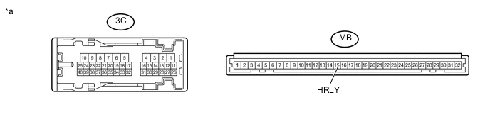
Text in Illustration *a Component without harness connected
(Instrument Panel Junction Block Assembly)
- - Standard Resistance Tester Connection Condition Specified Condition 3C-18 - MB-15 (HRLY) Always Below 1 Ω
OK
REPLACE MAIN BODY ECU Click here
NG
REPLACE INSTRUMENT PANEL JUNCTION BLOCK ASSEMBLY
-