FUEL LID LOCK CONTROL CABLE ASSEMBLY(for 5 Door) REMOVAL
PROCEDURE
-
REMOVE DECK BOARD ASSEMBLY
-
REMOVE SPARE WHEEL COVER (for TMMF Made)
-
REMOVE FRONT SEAT ASSEMBLY
-
REMOVE REAR SEAT ASSEMBLY (for 60/40 Split Seat Type LH Side)
-
REMOVE REAR SEAT ASSEMBLY (for 60/40 Split Seat Type RH Side)
-
REMOVE REAR CONSOLE BOX ASSEMBLY
-
REMOVE FRONT DOOR SCUFF PLATE RH
-
REMOVE FRONT DOOR SCUFF PLATE LH
Tech Tips
Use the same procedure as for the RH side.
-
REMOVE COWL SIDE TRIM BOARD RH
-
REMOVE COWL SIDE TRIM BOARD LH
Tech Tips
Use the same procedure as for the RH side.
-
REMOVE REAR DOOR SCUFF PLATE RH
-
REMOVE REAR DOOR SCUFF PLATE LH
Tech Tips
Use the same procedure as for the RH side.
-
REMOVE REAR FLOOR FINISH PLATE
-
SEPARATE REAR SEAT 3 POINT TYPE OUTER BELT ASSEMBLY LH
Tech Tips
Use the same procedure as for the RH side Click here.
-
SEPARATE REAR DOOR OPENING TRIM WEATHERSTRIP
-
Separate the rear door opening trim weatherstrip.
-
-
REMOVE NO. 2 ROOM LIGHT ASSEMBLY
-
REMOVE DECK TRIM SIDE PANEL ASSEMBLY LH
Tech Tips
Use the same procedure as for the RH side Click here.
-
REMOVE JACK COVER
-
REMOVE NO. 2 FLOOR CARPET HOOK
Tech Tips
Use the same procedure for both sides.
-
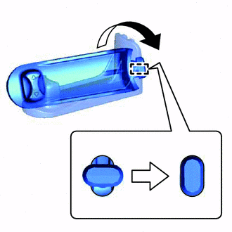
Rotate the No. 2 floor carpet hook 90° in the direction shown by the arrow in the illustration, disengage the hook and remove the No. 2 floor carpet hook.
-
-
REMOVE FRONT FLOOR CARPET ASSEMBLY
-
w/ Jack Assembly:
-
Remove the jack assembly.
-
-
Disengage the 6 clamps.
-
Remove the clip and the front floor carpet assembly.
-
-
REMOVE FUEL LID LOCK OPEN LEVER SUB-ASSEMBLY
-
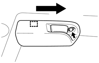
Remove the screw.
-
Disengage the guide and remove the fuel lid lock open lever sub-assembly in the direction indicated by the arrow as shown in the illustration.
-
Disengage the guide and disconnect the fuel lid lock control cable sub-assembly from the fuel lid lock open lever sub-assembly.
-
-
REMOVE FUEL LID LOCK CONTROL CABLE SUB-ASSEMBLY (for LHD)
-
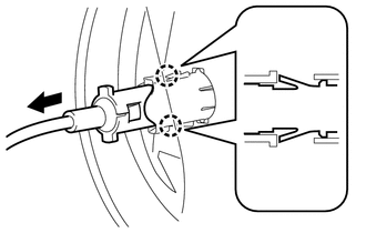
Disengage the 2 claws and separate the fuel lid lock control cable sub-assembly.
-
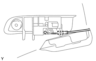
Remove the fuel lid lock control cable sub-assembly from the 4 clamps as shown in the illustration.
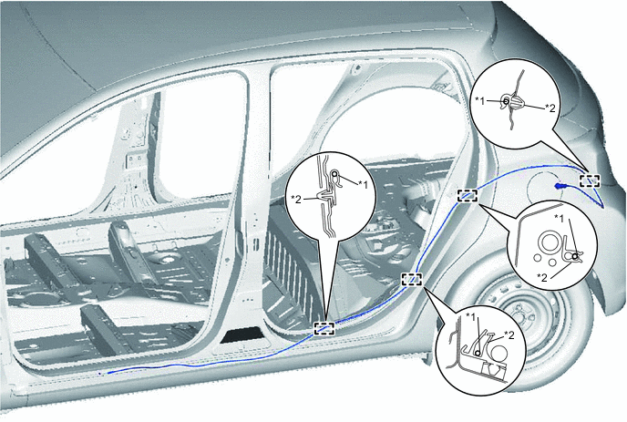
Text in Illustration *1 Fuel Lid Lock Control Cable Sub-assembly *2 Clamp
-
-
REMOVE FUEL LID LOCK CONTROL CABLE SUB-ASSEMBLY (for RHD)
-
Disengage the 2 claws and separate the fuel lid lock control cable sub-assembly.
-
Remove the fuel lid lock control cable sub-assembly from the 7 clamps as shown in the illustration.
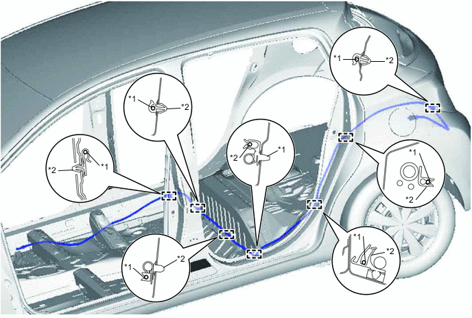
Text in Illustration *1 Fuel Lid Lock Control Cable Sub-assembly *2 Clamp
-
-
REMOVE FUEL FILLER OPENING LID LOCK RETAINER
-
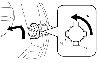
Text in Illustration *1 Claw A *a Slit *b Rotate Rotate the fuel filler opening lid lock retainer by 90° and disengage the 2 claws A from the 2 slits as shown in the illustration.
-
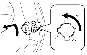
Text in Illustration *1 Claw B *a Slit *b Rotate Rotate the fuel filler opening lid lock retainer by another 90° and remove it by disengaging the 2 claws B from the 2 slits as shown in the illustration.
-