WINDOW DEFOGGER SYSTEM Rear Window Defogger System does not Operate
DESCRIPTION
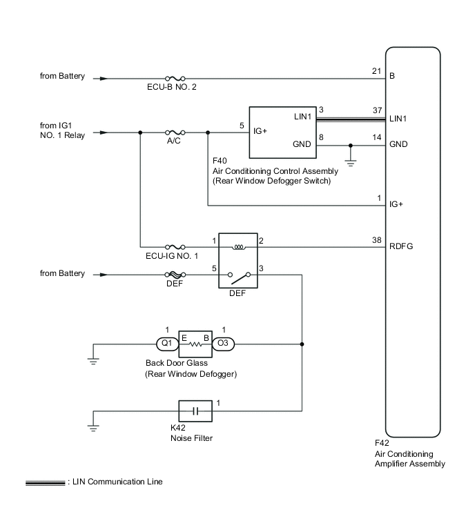
When the rear window defogger switch is turned on, a rear window defogger activation request signal is transmitted from the air conditioning control assembly to the air conditioning amplifier assembly. Upon receipt of the signal, the air conditioning amplifier assembly turns on the DEF relay to activate the rear window defogger system.
WIRING DIAGRAM
CAUTION / NOTICE / HINT
Note
Inspect the fuses for circuits related to this system before performing the following inspection procedure.
PROCEDURE
-
PERFORM ACTIVE TEST USING INTELLIGENT TESTER
-
Connect the intelligent tester to the DLC3.
-
Turn the ignition switch to ON.
-
Turn the intelligent tester on.
-
Enter the following menus: Body / Air Conditioner / Active Test.
-
According to the display on the intelligent tester, perform the Active Test.
Air Conditioner Tester Display Test Part Control Range Diagnostic Note Defogger Relay (Rear) DEF relay OFF or ON - OK The window defogger system operates normally.
OK 
GO TO AIR CONDITIONING SYSTEM Click here
NG 
-
-
INSPECT DEF RELAY
-
Inspect the DEF relay Click here.
NG
REPLACE DEF RELAY
OK
-
-
CHECK HARNESS AND CONNECTOR (DEF RELAY - IG1 NO. 1 RELAY AND BATTERY)
-
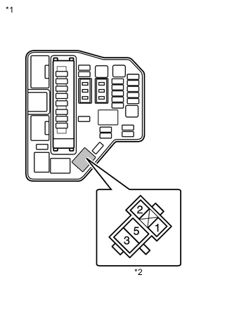
Text in Illustration *1 Engine Room Relay Block *2 DEF Relay Holder Remove the DEF relay from the engine room relay block.
-
Measure the voltage according to the value(s) in the table below.
Standard Voltage Tester Connection Switch Condition Specified Condition DEF-1 - Body ground Ignition switch ON 11 to 14 V DEF-5 - Body ground Always 11 to 14 V
NG
REPAIR OR REPLACE HARNESS OR CONNECTOR
OK
-
-
CHECK HARNESS AND CONNECTOR (DEF RELAY - AIR CONDITIONING AMPLIFIER ASSEMBLY)
-
Remove the DEF relay from the engine room relay block.
-
Disconnect the F42 air conditioning amplifier assembly connector.
-
Measure the resistance according to the value(s) in the table below.
Standard Resistance Tester Connection Condition Specified Condition DEF-2 - F42-38 (RDFG) Always Below 1 Ω DEF-2 - Body ground Always 10 kΩ or higher
NG
REPAIR OR REPLACE HARNESS OR CONNECTOR
OK
-
-
CHECK AIR CONDITIONING AMPLIFIER ASSEMBLY
-
Reconnect the F42 air conditioning amplifier assembly connector.
-
Reinstall the DEF relay.
-
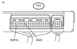
Text in Illustration *a Component with harness connected
(Air Conditioning Amplifier Assembly)
Remove the air conditioning amplifier assembly with its connectors still connected Click here.
-
Measure the voltage according to the value(s) in the table below.
Standard Voltage Tester Connection Switch Condition Specified Condition F42-38 (RDFG) - F42-14 (GND) Ignition switch ON
Rear window defogger switch ON
Below 1 V F42-38 (RDFG) - F42-14 (GND) Ignition switch ON
Rear window defogger switch OFF
11 to 14 V
NG
REPLACE AIR CONDITIONING AMPLIFIER ASSEMBLY Click here
OK
-
-
CHECK HARNESS AND CONNECTOR (BACK DOOR GLASS (REAR WINDOW DEFOGGER) - DEF RELAY AND BODY GROUND)
-
Disconnect the O3 and Q1 back door glass (rear window defogger) connectors.
-
Remove the DEF relay from the engine room relay block.
-
Measure the resistance according to the value(s) in the table below.
Standard Resistance Tester Connection Condition Specified Condition O3-1 (B) - DEF-3 Always Below 1 Ω Q1-1 (E) - Body ground Always Below 1 Ω O3-1 (B) - Body ground Always 10 kΩ or higher
OK
REPLACE BACK DOOR GLASS (REAR WINDOW DEFOGGER)
NG
REPAIR OR REPLACE HARNESS OR CONNECTOR
-