POWER WINDOW MASTER SWITCH INSPECTION
PROCEDURE
-
INSPECT POWER WINDOW REGULATOR MASTER SWITCH ASSEMBLY (w/ Rear Power Window)
-
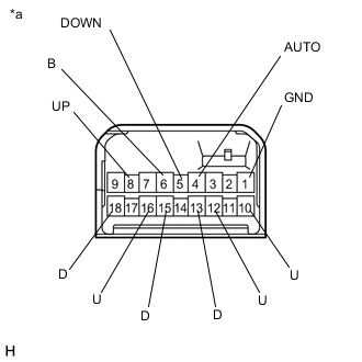
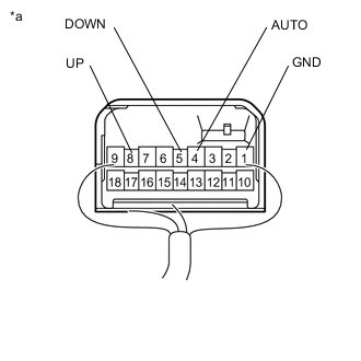
Text in Illustration *a Component without harness connected
(Power Window Regulator Master Switch Assembly)
Check the switch function (for LHD).
-
Turn the window lock switch off and operate the switches on the power window regulator master switch assembly.
-
Measure the resistance according to the value(s) in the table below.
Standard Resistance Driver Side Switch Tester Connection Condition Specified Condition 4 (AUTO) - 1 (GND) AUTO UP Below 1 Ω 8 (UP) - 1 (GND) AUTO UP Below 1 Ω 8 (UP) - 1 (GND) MANUAL UP Below 1 Ω 5 (DOWN) - 1 (GND) MANUAL DOWN Below 1 Ω 4 (AUTO) - 1 (GND) AUTO DOWN Below 1 Ω 5 (DOWN) - 1 (GND) AUTO DOWN Below 1 Ω Standard Resistance Front Passenger Side Switch Tester Connection Condition Specified Condition 6 (B) - 16 (U) UP Below 1 Ω 1 (GND) - 15 (D) UP Below 1 Ω 1 (GND) - 16 (U) OFF Below 1 Ω 1 (GND) - 15 (D) OFF Below 1 Ω 1 (GND) - 16 (U) DOWN Below 1 Ω 6 (B) - 15 (D) DOWN Below 1 Ω Standard Resistance Rear RH Side Switch Tester Connection Condition Specified Condition 6 (B) - 10 (U) UP Below 1 Ω 1 (GND) - 18 (D) UP Below 1 Ω 1 (GND) - 18 (D) OFF Below 1 Ω 1 (GND) - 10 (U) OFF Below 1 Ω 6 (B) - 18 (D) DOWN Below 1 Ω 1 (GND) - 10 (U) DOWN Below 1 Ω Standard Resistance Rear LH Side Switch Tester Connection Condition Specified Condition 6 (B) - 12 (U) UP Below 1 Ω 1 (GND) - 13 (D) UP Below 1 Ω 1 (GND) - 13 (D) OFF Below 1 Ω 1 (GND) - 12 (U) OFF Below 1 Ω 6 (B) - 13 (D) DOWN Below 1 Ω 1 (GND) - 12 (U) DOWN Below 1 Ω If the result is not as specified, replace the power window regulator master switch assembly.
-
-
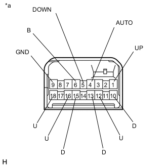
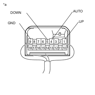
Text in Illustration *a Component without harness connected
(Power Window Regulator Master Switch Assembly)
Check the switch function (for RHD).
-
Turn the window lock switch off and operate the switches on the power window regulator master switch assembly.
-
Measure the resistance according to the value(s) in the table below.
Standard Resistance Driver Side Switch Tester Connection Condition Specified Condition 4 (AUTO) - 9 (GND) AUTO UP Below 1 Ω 1 (UP) - 9 (GND) AUTO UP Below 1 Ω 1 (UP) - 9 (GND) MANUAL UP Below 1 Ω 5 (DOWN) - 9 (GND) MANUAL DOWN Below 1 Ω 4 (AUTO) - 9 (GND) AUTO DOWN Below 1 Ω 5 (DOWN) - 9 (GND) AUTO DOWN Below 1 Ω Standard Resistance Front Passenger Side Switch Tester Connection Condition Specified Condition 6 (B) - 12 (U) UP Below 1 Ω 9 (GND) - 13 (D) UP Below 1 Ω 9 (GND) - 12 (U) OFF Below 1 Ω 9 (GND) - 13 (D) OFF Below 1 Ω 9 (GND) - 12 (U) DOWN Below 1 Ω 6 (B) - 13 (D) DOWN Below 1 Ω Standard Resistance Rear RH Side Switch Tester Connection Condition Specified Condition 6 (B) - 16 (U) UP Below 1 Ω 9 (GND) - 15 (D) UP Below 1 Ω 9 (GND) - 15 (D) OFF Below 1 Ω 9 (GND) - 16 (U) OFF Below 1 Ω 6 (B) - 15 (D) DOWN Below 1 Ω 9 (GND) - 16 (U) DOWN Below 1 Ω Standard Resistance Rear LH Side Switch Tester Connection Condition Specified Condition 6 (B) - 18 (U) UP Below 1 Ω 9 (GND) - 10 (D) UP Below 1 Ω 9 (GND) - 10 (D) OFF Below 1 Ω 9 (GND) - 18 (U) OFF Below 1 Ω 6 (B) - 10 (D) DOWN Below 1 Ω 9 (GND) - 18 (U) DOWN Below 1 Ω If the result is not as specified, replace the power window regulator master switch assembly.
-
-
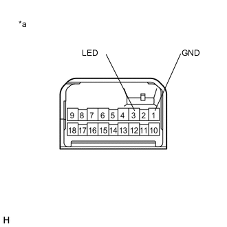
Text in Illustration *a Component without harness connected
(Power Window Regulator Master Switch Assembly)
Check that the LED illuminates (for LHD).
-
Apply auxiliary battery voltage to the power window regulator master switch assembly and check that the LED illuminates.
OK Measurement Condition Specified Condition Auxiliary battery positive (+) → Terminal 3 (LED)
Auxiliary battery negative (-) → Terminal 1 (GND)
LED illuminates If the result is not as specified, replace the power window regulator master switch assembly.
-
-
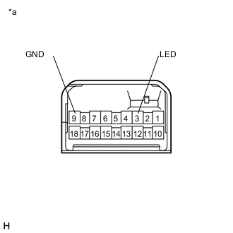
Text in Illustration *a Component without harness connected
(Power Window Regulator Master Switch Assembly)
Check that the LED illuminates (for RHD).
-
Apply auxiliary battery voltage to the power window regulator master switch assembly and check that the LED illuminates.
OK Measurement Condition Specified Condition Auxiliary battery positive (+) → Terminal 3 (LED)
Auxiliary battery negative (-) → Terminal 9 (GND)
LED illuminates If the result is not as specified, replace the power window regulator master switch assembly.
-
-
Text in Illustration *a Component with harness connected
(Power Window Regulator Master Switch Assembly)
Check the switch function (for LHD).
-
Reconnect the power window regulator master switch assembly connector.
-
Measure the voltage according to the value(s) in the table below.
Standard Voltage Tester Connection Switch Condition Specified Condition 8 (UP) - 1 (GND) Ignition switch ON, driver door power window regulator switch off 11 to 14 V 8 (UP) - 1 (GND) Ignition switch ON, driver door power window regulator switch up (Auto up position) Below 1 V 8 (UP) - 1 (GND) Ignition switch ON, driver door power window regulator switch up (Manual operation) Below 1 V 4 (AUTO) - 1 (GND) Ignition switch ON, driver door power window regulator switch off 11 to 14 V 4 (AUTO) - 1 (GND) Ignition switch ON, driver door power window regulator switch up (Auto up position) Below 1 V 4 (AUTO) - 1 (GND) Ignition switch ON, driver door power window regulator switch down (Auto down position) Below 1 V 5 (DOWN) - 1 (GND) Ignition switch ON, driver door power window regulator switch off 11 to 14 V 5 (DOWN) - 1 (GND) Ignition switch ON, driver door power window regulator switch down (Auto down position) Below 1 V 5 (DOWN) - 1 (GND) Ignition switch ON, driver door power window regulator switch down (Manual operation) Below 1 V If the result is not as specified, replace the power window regulator master switch assembly.
-
-
Text in Illustration *a Component with harness connected
(Power Window Regulator Master Switch Assembly)
Check the switch function (for RHD).
-
Reconnect the power window regulator master switch assembly connector.
-
Measure the voltage according to the value(s) in the table below.
Standard Voltage Tester Connection Switch Condition Specified Condition 1 (UP) - 9 (GND) Ignition switch ON, driver door power window regulator switch off 11 to 14 V 1 (UP) - 9 (GND) Ignition switch ON, driver door power window regulator switch up (Auto up position) Below 1 V 1 (UP) - 9 (GND) Ignition switch ON, driver door power window regulator switch up (Manual operation) Below 1 V 4 (AUTO) - 9 (GND) Ignition switch ON, driver door power window regulator switch off 11 to 14 V 4 (AUTO) - 9 (GND) Ignition switch ON, driver door power window regulator switch up (Auto up position) Below 1 V 4 (AUTO) - 9 (GND) Ignition switch ON, driver door power window regulator switch down (Auto down position) Below 1 V 5 (DOWN) - 9 (GND) Ignition switch ON, driver door power window regulator switch off 11 to 14 V 5 (DOWN) - 9 (GND) Ignition switch ON, driver door power window regulator switch down (Auto down position) Below 1 V 5 (DOWN) - 9 (GND) Ignition switch ON, driver door power window regulator switch down (Manual operation) Below 1 V If the result is not as specified, replace the power window regulator master switch assembly.
-
-
-
INSPECT POWER WINDOW REGULATOR MASTER SWITCH ASSEMBLY (w/o Rear Power Window)
-
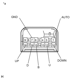
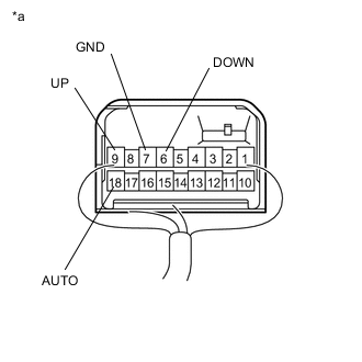
Text in Illustration *a Component without harness connected
(Power Window Regulator Master Switch Assembly)
Check the switch function (for LHD).
-
Turn the window lock switch off and operate the switches on the power window regulator master switch assembly.
-
Measure the resistance according to the value(s) in the table below.
Standard Resistance Driver Side Switch Tester Connection Condition Specified Condition 1 (AUTO) - 7 (GND) AUTO UP Below 1 Ω 18 (UP) - 7 (GND) AUTO UP Below 1 Ω 18 (UP) - 7 (GND) MANUAL UP Below 1 Ω 10 (DOWN) - 7 (GND) MANUAL DOWN Below 1 Ω 1 (AUTO) - 7 (GND) AUTO DOWN Below 1 Ω 10 (DOWN) - 7 (GND) AUTO DOWN Below 1 Ω Standard Resistance Front Passenger Side Switch Tester Connection Condition Specified Condition 15 (B) - 12 (U) UP Below 1 Ω 7 (GND) - 16 (D) UP Below 1 Ω 7 (GND) - 12 (U) OFF Below 1 Ω 7 (GND) - 16 (D) OFF Below 1 Ω 7 (GND) - 12 (U) DOWN Below 1 Ω 15 (B) - 16 (D) DOWN Below 1 Ω If the result is not as specified, replace the power window regulator master switch assembly.
-
-
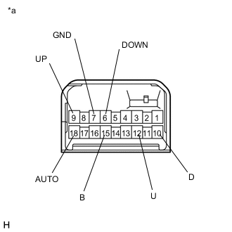
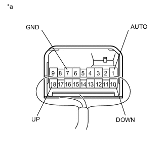
Text in Illustration *a Component without harness connected
(Power Window Regulator Master Switch Assembly)
Check the switch function (for RHD).
-
Turn the window lock switch off and operate the switches on the power window regulator master switch assembly.
-
Measure the resistance according to the value(s) in the table below.
Standard Resistance Driver Side Switch Tester Connection Condition Specified Condition 18 (AUTO) - 7 (GND) AUTO UP Below 1 Ω 9 (UP) - 7 (GND) AUTO UP Below 1 Ω 9 (UP) - 7 (GND) MANUAL UP Below 1 Ω 6 (DOWN) - 7 (GND) MANUAL DOWN Below 1 Ω 18 (AUTO) - 7 (GND) AUTO DOWN Below 1 Ω 6 (DOWN) - 7 (GND) AUTO DOWN Below 1 Ω Standard Resistance Front Passenger Side Switch Tester Connection Condition Specified Condition 15 (B) - 12 (U) UP Below 1 Ω 7 (GND) - 10 (D) UP Below 1 Ω 7 (GND) - 12 (U) OFF Below 1 Ω 7 (GND) - 10 (D) OFF Below 1 Ω 7 (GND) - 12 (U) DOWN Below 1 Ω 15 (B) - 10 (D) DOWN Below 1 Ω If the result is not as specified, replace the power window regulator master switch assembly.
-
-
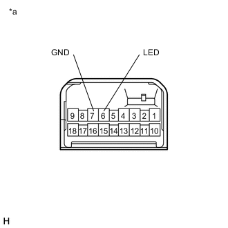
Text in Illustration *a Component without harness connected
(Power Window Regulator Master Switch Assembly)
Check that the LED illuminates (for LHD).
-
Apply auxiliary battery voltage to the power window regulator master switch assembly and check that the LED illuminates.
OK Measurement Condition Specified Condition Auxiliary battery positive (+) → Terminal 6 (LED)
Auxiliary battery negative (-) → Terminal 7 (GND)
LED illuminates If the result is not as specified, replace the power window regulator master switch assembly.
-
-
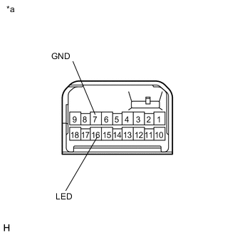
Text in Illustration *a Component without harness connected
(Power Window Regulator Master Switch Assembly)
Check that the LED illuminates (for RHD).
-
Apply auxiliary battery voltage to the power window regulator master switch assembly and check that the LED illuminates.
OK Measurement Condition Specified Condition Auxiliary battery positive (+) → Terminal 16 (LED)
Auxiliary battery negative (-) → Terminal 7 (GND)
LED illuminates If the result is not as specified, replace the power window regulator master switch assembly.
-
-
Text in Illustration *a Component with harness connected
(Power Window Regulator Master Switch Assembly)
Check the switch function (for LHD).
-
Reconnect the power window regulator master switch assembly connector.
-
Measure the voltage according to the value(s) in the table below.
Standard Voltage Tester Connection Switch Condition Specified Condition 18 (UP) - 7 (GND) Ignition switch ON, driver door power window regulator switch off 11 to 14 V 18 (UP) - 7 (GND) Ignition switch ON, driver door power window regulator switch up (Auto up position) Below 1 V 18 (UP) - 7 (GND) Ignition switch ON, driver door power window regulator switch up (Manual operation) Below 1 V 1 (AUTO) - 7 (GND) Ignition switch ON, driver door power window regulator switch off 11 to 14 V 1 (AUTO) - 7 (GND) Ignition switch ON, driver door power window regulator switch up (Auto up position) Below 1 V 1 (AUTO) - 7 (GND) Ignition switch ON, driver door power window regulator switch down (Auto down position) Below 1 V 10 (DOWN) - 7 (GND) Ignition switch ON, driver door power window regulator switch off 11 to 14 V 10 (DOWN) - 7 (GND) Ignition switch ON, driver door power window regulator switch down (Auto down position) Below 1 V 10 (DOWN) - 7 (GND) Ignition switch ON, driver door power window regulator switch down (Manual operation) Below 1 V If the result is not as specified, replace the power window regulator master switch assembly.
-
-
Text in Illustration *a Component with harness connected
(Power Window Regulator Master Switch Assembly)
Check the switch function (for RHD).
-
Reconnect the power window regulator master switch assembly connector.
-
Measure the voltage according to the value(s) in the table below.
Standard Voltage Tester Connection Switch Condition Specified Condition 9 (UP) - 7 (GND) Ignition switch ON, driver door power window regulator switch off 11 to 14 V 9 (UP) - 7 (GND) Ignition switch ON, driver door power window regulator switch up (Auto up position) Below 1 V 9 (UP) - 7 (GND) Ignition switch ON, driver door power window regulator switch up (Manual operation) Below 1 V 18 (AUTO) - 7 (GND) Ignition switch ON, driver door power window regulator switch off 11 to 14 V 18 (AUTO) - 7 (GND) Ignition switch ON, driver door power window regulator switch up (Auto up position) Below 1 V 18 (AUTO) - 7 (GND) Ignition switch ON, driver door power window regulator switch down (Auto down position) Below 1 V 6 (DOWN) - 7 (GND) Ignition switch ON, driver door power window regulator switch off 11 to 14 V 6 (DOWN) - 7 (GND) Ignition switch ON, driver door power window regulator switch down (Auto down position) Below 1 V 6 (DOWN) - 7 (GND) Ignition switch ON, driver door power window regulator switch down (Manual operation) Below 1 V If the result is not as specified, replace the power window regulator master switch assembly.
-
-