LOWER INSTRUMENT PANEL INSTALLATION
PROCEDURE
-
INSTALL LOWER INSTRUMENT PANEL SUB-ASSEMBLY
-
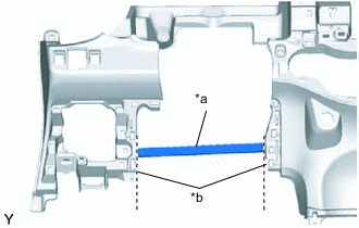
Text in Illustration *a Runner Portion *b Cut Off Using a nipper, cut off both ends of the runner portion shown in the illustration (When installing a new one).
-
Engage the 10 guides and install the lower instrument panel.
-
for TMC Made:
-
Install the lower instrument panel with the 6 <B> or <C> bolts, <D> or <E> screw, 2 <F> or <H> or <I> bolts and bolt.
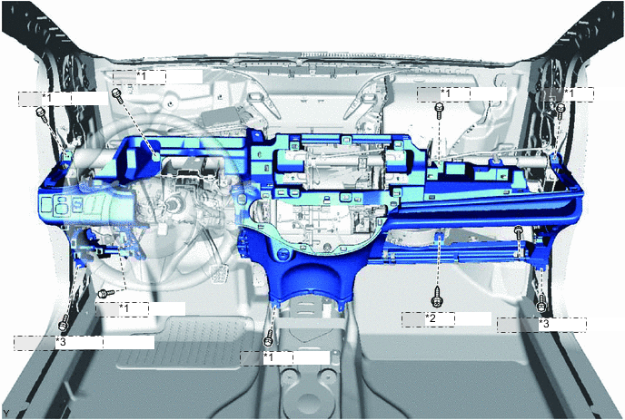
*1 <B> or <C> *2 <D> or <E> *3 <F> or <H> or <I>
-
-
for TMMF Made:
-
Install the lower instrument panel with the 6 <B> or <C> bolts, <D> or <E> screw, 2 <F> bolts and bolt.
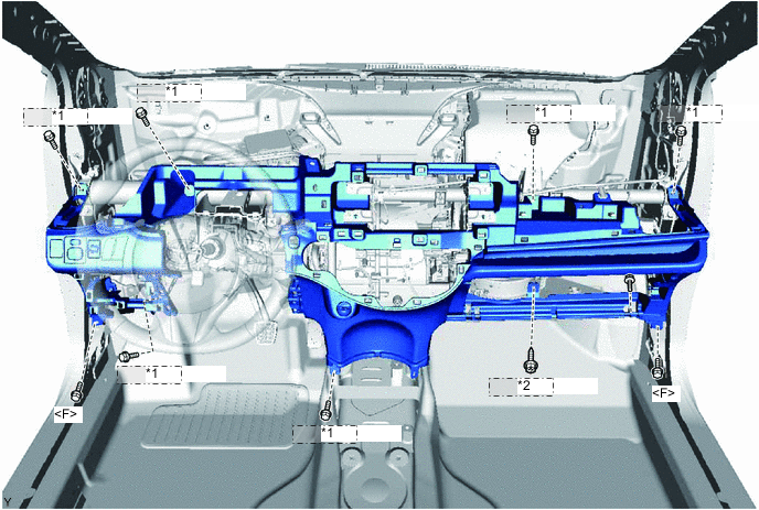
*1 <B> or <C> *2 <D> or <E>
-
-
Connect the clamps and connectors.
-
Engage the 2 claws and install the DLC3 connector.
-
-
INSTALL HOOD LOCK CONTROL LEVER SUB-ASSEMBLY
-
Engage the 3 claws and install the hood lock control lever.
-
-
INSTALL REAR CONSOLE BOX ASSEMBLY
-
INSTALL AIR CONDITIONING CONTROL ASSEMBLY (for LHD Automatic Air Conditioning System)
-
INSTALL AIR CONDITIONING CONTROL ASSEMBLY (for RHD Automatic Air Conditioning System)
-
CONNECT AIR MIX DAMPER CONTROL CABLE SUB-ASSEMBLY (for Manual Air Conditioning System)
-
CONNECT AIR INLET DAMPER CONTROL CABLE SUB-ASSEMBLY (for Manual Air Conditioning System)
-
CONNECT DEFROSTER DAMPER CONTROL CABLE SUB-ASSEMBLY (for Manual Air Conditioning System)
-
INSTALL AIR CONDITIONING PANEL ASSEMBLY (for Manual Air Conditioning System)
-
INSTALL STEREO OPENING COVER WITH BRACKET (w/o Radio Receiver)
-
Align the 2 holes in the radio bracket with the 2 bosses of the instrument panel.
-
Install the radio stereo opening cover with bracket with the 4 screws.
-
-
INSTALL RADIO RECEIVER ASSEMBLY WITH BRACKET (w/ Radio Receiver)
-
INSTALL LOWER INSTRUMENT PANEL FINISH PANEL (w/o Knee Airbag)
-
for LHD:
-
Engage the 5 claws and 2 clips and install the instrument panel finish panel.
-
-
for RHD:
-
Engage the 6 claws and 2 clips and install the instrument panel finish panel.
-
-
-
INSTALL LOWER NO. 1 INSTRUMENT PANEL AIRBAG ASSEMBLY (w/ Knee Airbag)
-
INSTALL LOWER NO. 2 INSTRUMENT PANEL FINISH PANEL (for LHD)
-
Engage the 3 claws and 5 clips and install the instrument panel finish panel.
-
-
INSTALL NO. 1 INSTRUMENT PANEL UNDER COVER SUB-ASSEMBLY
-
w/ Footwell Light:
-
Connect the connector.
-
-
Engage the guide and the claw.
-
Install the instrument panel under cover with the 2 <A> screws.
-
-
INSTALL NO. 2 INSTRUMENT PANEL UNDER COVER SUB-ASSEMBLY
-
w/ Footwell Light:
-
Connect the connector.
-
-
Engage the guide and the 3 claws and install the instrument panel under cover.
-
-
INSTALL GLOVE COMPARTMENT DOOR ASSEMBLY
-
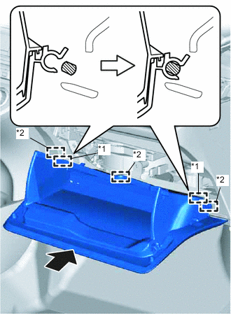
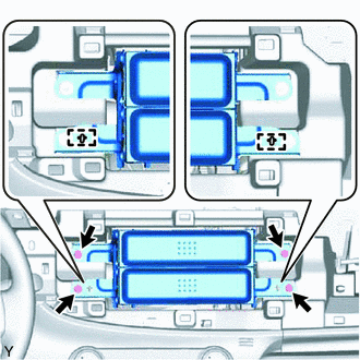
Text in Illustration *1 Hinge *2 Guide Engage the 3 guides and 2 hinges in the horizontal direction to install the glove compartment door.
Note
Engage the 2 hinges in the horizontal direction, otherwise, installation failure caused by excessive play around the hinges will result.
-
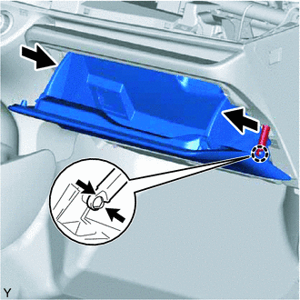
While pushing in the sides of the glove compartment door as indicated by the arrows in the illustration, close the door to engage it to the 2 stoppers.
-
Engage the claw and connect the glove compartment door stopper.
-
-
INSTALL UPPER INSTRUMENT PANEL SUB-ASSEMBLY