AIR CONDITIONING PRESSURE SENSOR(for TMMF Made) ON-VEHICLE INSPECTION
PROCEDURE
-
INSPECT AIR CONDITIONER PRESSURE SENSOR (for Manual Air Conditioning System)
-

Text in Illustration *a Front view of wire harness connector
(to Air Conditioner Pressure Sensor)
Check the wire harness.
-
Disconnect the A23 air conditioner pressure sensor connector.
-
Measure the resistance according to the value(s) in the table below.
Standard Resistance Tester Connection Condition Specified Condition A23-1 (-) - Body ground Always Below 1 Ω -
Turn the ignition switch to ON.
-
Measure the voltage according to the value(s) in the table below.
Standard Voltage Tester Connection Switch Condition Specified Condition A23-3 (+) - Body ground Ignition switch ON 4.75 to 5.25 V
-
-
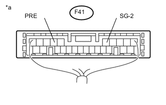
Text in Illustration *a Component with harness connected
(Air Conditioning Amplifier Assembly)
Check the air conditioner pressure sensor.
-
Set the manifold gauge.
-
Connect the connector to the air conditioner pressure sensor.
-
Warm up the engine.
-
A/C switch on.
-
Using a voltmeter, measure the voltage between connector terminals 7 (PRE) and 5 (SG-2) of the air conditioning amplifier assembly.
Tech Tips
Check from the rear of the connector while it is connected to the air conditioning amplifier assembly.
Standard Voltage Tester Connection Refrigerant Pressure Specified Condition 7 (PRE) - 5 (SG-2) 0.196 to 3.14 MPa
(2.0 to 32 kgf/cm2, 28 to 455 psi)
0.66 to 4.88 V
-
-
-
INSPECT AIR CONDITIONER PRESSURE SENSOR (for Automatic Air Conditioning System)
-
Text in Illustration *a Front view of wire harness connector
(to Air Conditioner Pressure Sensor)
Check the wire harness.
-
Disconnect the connector of the air conditioner pressure sensor.
-
Using an ohmmeter, measure the resistance of the wire harness side connector.
Standard Resistance Tester Connection Condition Specified Condition A23-1 (-) - Body ground Always Below 1 Ω -
Turn the ignition switch to ON.
-
Measure the voltage of the wire harness side connector.
Standard Voltage Tester Connection Switch Condition Specified Condition A23-3 (+) - Body ground Ignition switch ON 4.75 to 5.25 V
-
-
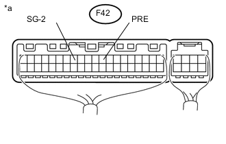
Text in Illustration *a Component with harness connected
(Air Conditioning Amplifier Assembly)
Check the air conditioner pressure sensor.
-
Set the manifold gauge.
-
Connect the connector to the air conditioner pressure sensor.
-
Warm up the engine.
-
A/C switch on.
-
Using a voltmeter, measure the voltage between connector terminals 9 (PRE) and 13 (SG-2) of the air conditioning amplifier assembly.
Tech Tips
Check from the rear of the connector while it is connected to the air conditioning amplifier assembly.
Standard Voltage Tester Connection Refrigerant Pressure Specified Condition F42-9 (PRE) - F42-13 (SG-2) 0.196 to 3.14 MPa
(2.0 to 32 kgf/cm2, 28 to 455 psi)
0.66 to 4.88 V
-
-