COMPRESSOR(for 1NR-FE) INSTALLATION
PROCEDURE
-
INSPECT COMPRESSOR OIL
-
Remove the suction seal cap.
-
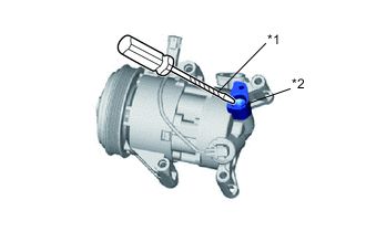
Text in Illustration *1 Protective Tape *2 VST valve (Valve Inside Suction Port Using a screwdriver with its tip wrapped in protective tape, insert the screwdriver through the suction port and set the VST valve (valve inside suction port) to the open position.
Note
Be sure not to damage the piping contact surfaces with the tip of the screwdriver.
-
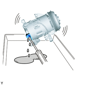
Lightly shake the compressor with the suction port facing down, and drain the oil (*1).
Note
Do not allow the pulley to come into contact with the compressor oil.
-
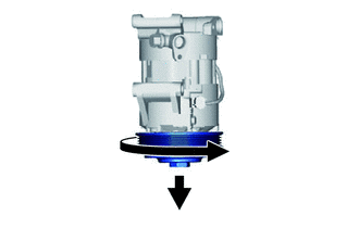
With the pulley facing down, rotate the pulley in the direction shown by the arrow 10 times at a rate of approximately once every 2 seconds (*2).
Note
If the pulley is rotated, refrigerant or oil might splash out. Thus, keep your face away from the compressor port.
-
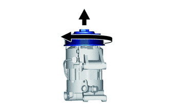
Rotate the pulley once in the direction shown by the arrow while quickly turning the compressor so the pulley is up (*3).
-
Proceed with the above procedure (*1) and drain the oil (*4).
-
Drain the oil by repeating the procedures above approximately 5 times (from (*2) to (*4)).
Standard (Amount of Oil to be Removed) Standard (Amount of Oil to be Removed) Amount of Oil Inside a New Compressor 30 cm3
60 cm3
Tech Tips
If too much oil has been removed, set the VST valve to the open position through the suction port, and add oil.
-
-
INSTALL COMPRESSOR WITH PULLEY ASSEMBLY (for TMC Made)
-
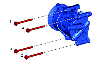
Install the compressor with the 4 bolts.
Tech Tips
Tighten the bolts in the order shown in the illustration.
- Torque:
- 25 N*m { 250 kgf*cm, 18 ft.*lbf }
-
Connect the connector.
-
-
INSTALL COMPRESSOR WITH PULLEY ASSEMBLY (for TMMF Made)
-
Using a "TORX" socket wrench (E8), install the compressor with the 2 stud bolts.
- Torque:
- 9.8 N*m { 100 kgf*cm, 87 in.*lbf }
-
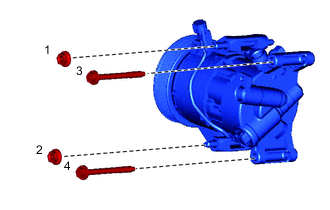
Install the 2 bolts and the 2 nuts.
Tech Tips
Tighten the bolts in the order shown in the illustration.
- Torque:
- 25 N*m { 250 kgf*cm, 18 ft.*lbf }
-
Connect the connector.
-
-
CONNECT NO. 1 COOLER REFRIGERANT DISCHARGE HOSE
-
Remove the attached vinyl tape from the discharge hose.
-
Apply sufficient compressor oil to a new O-ring and the fitting surface of the compressor.
Compressor oil ND-OIL 8 or equivalent -
Install the O-ring onto the discharge hose.
-
Install the discharge hose onto the compressor with the bolt.
- Torque:
- 9.8 N*m { 100 kgf*cm, 87 in.*lbf }
-
-
CONNECT SUCTION HOSE SUB-ASSEMBLY
-
Remove the attached vinyl tape from the suction hose.
-
Apply sufficient compressor oil to a new O-ring and the fitting surface of the compressor.
Compressor oil ND-OIL 8 or equivalent -
Install the O-ring onto the suction hose.
-
Install the suction hose onto the compressor with the bolt.
- Torque:
- 9.8 N*m { 100 kgf*cm, 87 in.*lbf }
-
-
INSTALL ENGINE UNDER COVER RH
-
INSTALL FAN AND GENERATOR V BELT
-
CHARGE REFRIGERANT
-
WARM UP ENGINE
-
INSPECT FOR REFRIGERANT LEAK