AIR CONDITIONING UNIT INSTALLATION
PROCEDURE
-
INSTALL NO. 2 AIR DUCT
-
Engage the 3 claws to install the No. 2 air duct.
-
-
INSTALL NO. 1 AIR DUCT
-
Engage the 3 claws to install the No. 1 air duct.
-
-
INSTALL COOLER AIR HOSE (for Automatic Air Conditioning System)
-
Install the cooler air hose.
-
-
INSTALL AIR CONDITIONING RADIATOR ASSEMBLY
-
Install the air conditioning radiator with the 3 screws.
-
-
INSTALL AIR CONDITIONING AMPLIFIER ASSEMBLY (for Automatic Air Conditioning System)
-
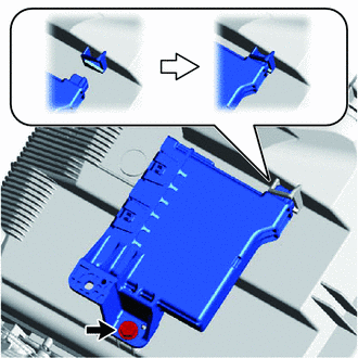
Engage the claw to install the air conditioning amplifier assembly as shown in the illustration.
-
Tighten the screw.
-
-
INSTALL AIR CONDITIONING AMPLIFIER ASSEMBLY (for Manual Air Conditioning System)
-
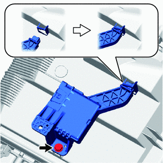
Engage the claw to install the air conditioning amplifier assembly as shown in the illustration.
-
Tighten the screw.
-
-
INSTALL AIR CONDITIONING HARNESS ASSEMBLY (for LHD)
-
Connect the connectors to engage the clamps, then install the air conditioning harness assembly.
-
-
INSTALL AIR CONDITIONING HARNESS ASSEMBLY (for RHD)
-
Connect the connectors to engage the clamps, then install the air conditioning harness assembly.
-
-
TEMPORARILY TIGHTEN AIR CONDITIONER UNIT ASSEMBLY
-
Temporarily tighten the air conditioning unit assembly with the 3 bolts and nut.
Note
To prevent damage to the installation bracket for the air conditioning unit assembly, be sure to support the air conditioning unit in place.
-
-
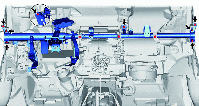
INSTALL INSTRUMENT PANEL REINFORCEMENT
-
Install the instrument panel reinforcement with the 8 bolts.
-
-
INSTALL REAR NO. 1 AIR DUCT (for Cold Area Specification Vehicles)
-
Engage the 2 claws to install the rear No. 1 air duct.
-
-
INSTALL NO. 1 INSTRUMENT PANEL BRACE SUB-ASSEMBLY
-
Install the instrument panel brace sub-assembly with the 2 bolts, nut and screw.
-
-
INSTALL AIR CONDITIONER UNIT ASSEMBLY (for LHD)
-
Install the air duct with the 2 bolts.
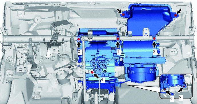
- Torque:
- 9.8 N*m { 100 kgf*cm, 87 in.*lbf }
-
Install the bolt, nut and 4 screws in the order shown in the illustration.
- Torque:
- Bolt
- 9.8 N*m { 100 kgf*cm, 87 in.*lbf }
-
-
INSTALL AIR CONDITIONER UNIT ASSEMBLY (for RHD)
-
Install the air duct with the 2 bolts.
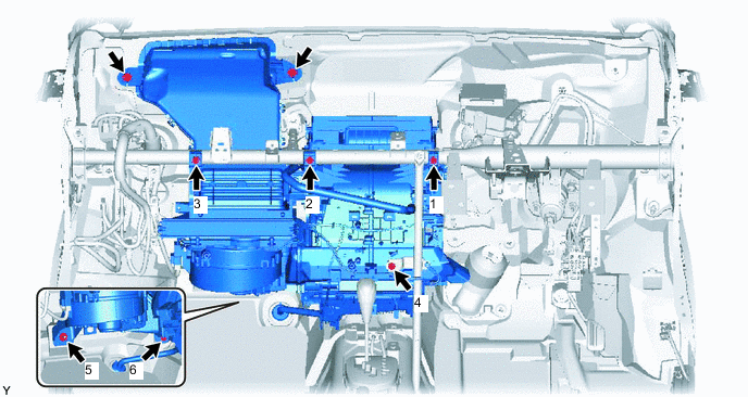
- Torque:
- 9.8 N*m { 100 kgf*cm, 87 in.*lbf }
-
Install the bolt, nut and 4 screws in the order shown in the illustration.
- Torque:
- Bolt
- 9.8 N*m { 100 kgf*cm, 87 in.*lbf }
-
-
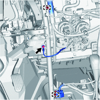
INSTALL INSTRUMENT PANEL WIRE (for LHD)
-
Connect the connectors to engage the clamps, then install the instrument panel wire.
-
Install the ground wire with the bolts.
- Torque:
- 8.4 N*m { 86 kgf*cm, 74 in.*lbf }
-
for Automatic Air Conditioning System:
-
Engage the clamp to connect the instrument panel wire.
-
Connect the 2 connectors.
-
-
for Manual Air Conditioning System:
-
Engage the 3 clamps to disconnect the instrument panel wire.
-
Connect the 3 connectors.
-
-
Connect the 3 clamps to install the connector holders.
-
Tighten the bolt.
- Torque:
- 8.4 N*m { 86 kgf*cm, 74 in.*lbf }
-
Connect the connectors.
-
Install the connector holder with the screw.
-
Connect the 2 clamps to install the connector holders.
-
Tighten the screw.
-
Connect the connectors.
-
Connect the 2 clamps.
-
for Cold Area Specification Vehicles:
-
Install the ground wire with the bolt.
- Torque:
- 8.4 N*m { 86 kgf*cm, 74 in.*lbf }
-
-
-
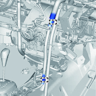
INSTALL INSTRUMENT PANEL WIRE (for RHD)
-
Connect the connectors to engage the clamps, then install the instrument panel wire.
-
Install the ground wire with the bolts.
- Torque:
- 8.4 N*m { 86 kgf*cm, 74 in.*lbf }
-
for Automatic Air Conditioning System:
-
Engage the 3 clamps to connect the instrument panel wire.
-
Connect the 2 connectors.
-
-
for Manual Air Conditioning System:
-
Engage the 5 clamps to disconnect the instrument panel wire.
-
Connect the 3 connectors.
-
-
Connect the 3 clamps to install the connector holders.
-
Tighten the bolt.
- Torque:
- 8.4 N*m { 86 kgf*cm, 74 in.*lbf }
-
Connect the connectors.
-
Install the connector holder with the screw.
-
Connect the 2 clamps to install the connector holders.
-
Tighten the screw.
-
Connect the connectors.
-
Connect the 2 clamps.
-
-
INSTALL INSTRUMENT PANEL JUNCTION BLOCK ASSEMBLY
-
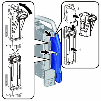
Connect the back side connectors to install the instrument panel junction block assembly in the order as shown in the illustration.
Note
Securely connect the connector.
-
Install the instrument panel junction block assembly with the bolt.
- Torque:
- 8.4 N*m { 86 kgf*cm, 74 in.*lbf }
-
Connect the front side connectors as shown in the illustration.
Note
Securely connect the connector.
-
Engage the clamps.
-
-
CONNECT DRAIN COOLER HOSE
-
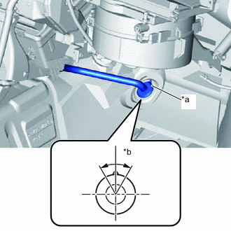
*a UP Mark *b 60° Install the drain cooler hose as shown in the illustration.
Note
-
Install the drain hose with its UP mark facing upward, within the 60 degree range shown in the illustration.
-
Install the drain hose without twisting it.
-
-
-
INSTALL REAR NO. 3 AIR DUCT (for Cold Area Specification Vehicles)
-
Install the 2 claws to install the rear No. 3 air duct.
-
-
INSTALL REAR NO. 4 AIR DUCT (for Cold Area Specification Vehicles)
-
Install the 2 claws to install the rear No. 4 air duct.
-
-
INSTALL REAR NO. 2 AIR DUCT (for Cold Area Specification Vehicles)
-
Install the 2 claws to install the rear No. 2 air duct.
-
Return the floor carpet.
-
-
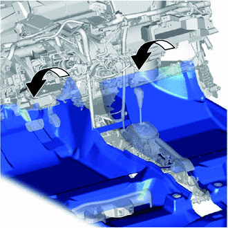
INSTALL DEFROSTER NOZZLE ASSEMBLY
-
Engage the 2 claws and 3 guides, then install the defroster nozzle assembly.
-
Engage the clamps to connect the connectors, then connect the wire harness.
-
-
INSTALL NAVIGATION ANTENNA ASSEMBLY (w/ Navigation System)
-
INSTALL HEATER TO REGISTER DUCT ASSEMBLY (w/ Navigation System)
-
Engage the 3 claws to install the heater to register duct assembly.
-
Engage the clamp to connect the wire harness.
-
-
INSTALL HEATER TO REGISTER DUCT ASSEMBLY (w/o Navigation System)
-
Engage the 3 claws to install the heater to register duct assembly.
-
-
INSTALL STEERING COLUMN ASSEMBLY (for LHD)
-
INSTALL STEERING COLUMN ASSEMBLY (for RHD)
-
INSTALL LOWER INSTRUMENT PANEL SUB-ASSEMBLY
-
CONNECT WATER HOSE SUB-ASSEMBLY (for TMC Made)
-
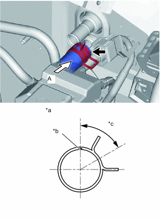
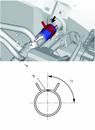
*a View A *b White Paint Mark *c 60° Connect the water hose sub-assembly onto the air conditioning unit.
Tech Tips
Perform the installation with the hose clip and mark at the correct angle.
-
-
CONNECT WATER HOSE SUB-ASSEMBLY B (for TMC Made)
-
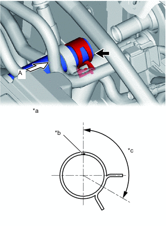
*a View A *b White Paint Mark *c 90° Connect the water hose sub-assembly onto the air conditioning unit.
Tech Tips
Perform the installation with the hose clip and mark at the correct angle.
-
-
CONNECT WATER HOSE SUB-ASSEMBLY (for TMMF Made)
-
*a View A *b White Paint Mark *c 120° Connect the water hose sub-assembly onto the air conditioning unit.
Tech Tips
Perform the installation with the hose clip and mark at the correct angle.
-
-
CONNECT WATER HOSE SUB-ASSEMBLY B (for TMMF Made)
-
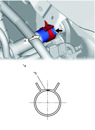
*a View A *b White Paint Mark Connect the water hose sub-assembly onto the air conditioning unit.
Tech Tips
Perform the installation with the hose clip and mark at the correct angle.
-
-
INSTALL FUEL FILTER ASSEMBLY WITH SUPPORT (for 1ND-TV)
-
CONNECT LIQUID TUBE SUB-ASSEMBLY A
-
Remove the vinyl tape from liquid tube and the connecting portion of the unit.
-
Apply sufficient compressor oil to a new O-ring and the connecting part of the liquid tube sub-assembly A.
Compressor oil for HFC-134a (R134a) ND-OIL 8 or equivalent for HFO-1234yf (R1234yf) ND-OIL 12 or equivalent -
Install the O-ring onto the liquid tube sub-assembly A.
-
Connect the liquid tube to the unit.
-
-
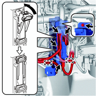
CONNECT SUCTION TUBE SUB-ASSEMBLY B
-
Remove the vinyl tape from suction tube sub-assembly B and the connecting portion of the unit.
-
Apply sufficient compressor oil to a new O-ring and the connecting part of the suction tube.
Compressor oil for HFC-134a (R134a) ND-OIL 8 or equivalent for HFO-1234yf (R1234yf) ND-OIL 12 or equivalent -
Install the O-ring onto the suction tube.
-
Securely connect the suction tube to the air conditioning unit.
-
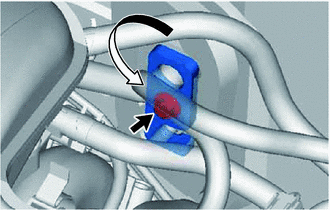
Turn the hook connector in the direction indicated by the arrow in the illustration.
-
Insert the pipe joints securely into the fitting holes and tighten the bolt.
- Torque:
- 9.8 N*m { 100 kgf*cm, 87 in.*lbf }
-
-
INSTALL BOOSTER VACUUM TUBE (for 1ND-TV)
-
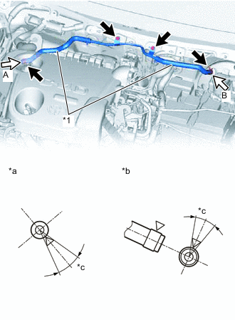
*1 Vacuum Hose *a View A *b View B *c 30° Install the booster vacuum tube with the 2 bolts.
- Torque:
- 8.3 N*m { 85 kgf*cm, 73 in.*lbf }
-
Connect the 2 hoses onto the vacuum pump and brake booster.
Tech Tips
Perform the installation with the hose clip at the correct angle.
-
-
INSTALL OUTER COWL TOP PANEL
-
INSTALL INNER COWL TOP TO COWL BRACE
-
INSTALL FRONT AIR SHUTTER SEAL RH
-
INSTALL FRONT NO. 1 VENTILATOR SEAL
-
INSTALL WINDSHIELD WIPER MOTOR AND LINK
-
CONNECT CABLE TO NEGATIVE BATTERY TERMINAL
- Torque:
- 5.4 N*m { 55 kgf*cm, 48 in.*lbf }
-
ADD ENGINE COOLANT (for 1KR-FE)
-
ADD ENGINE COOLANT (for 2NR-FKE)
-
ADD ENGINE COOLANT (for 1ND-TV)
-
ADD ENGINE COOLANT (for 2ZR-FE)
-
BLEED AIR FROM FUEL SYSTEM
-
CHARGE REFRIGERANT
-
for HFC-134a (R134a):
-
for HFO-1234yf (R1234yf):
-
-
INSPECT FOR COOLANT LEAK (for 1KR-FE)
-
INSPECT FOR COOLANT LEAK (for 2NR-FKE)
-
INSPECT COOLANT LEAK (for 1ND-TV)
-
INSPECT COOLANT LEAK (for 2ZR-FE)
-
INSPECT FOR FUEL LEAK
-
WARM UP ENGINE
-
for HFC-134a (R134a):
-
for HFO-1234yf (R1234yf):
-
-
INSPECT FOR REFRIGERANT LEAK
-
for HFC-134a (R134a):
-
for HFO-1234yf (R1234yf):
-