AIR CONDITIONING UNIT REMOVAL
CAUTION / NOTICE / HINT
CAUTION:
Some of these service operations affect the SRS airbag system. Read the precautionary notices concerning the SRS airbag system before servicing.
PROCEDURE
-
PRECAUTION
Note
After turning the ignition switch off, waiting time may be required before disconnecting the cable from the battery terminal. Therefore, make sure to read the disconnecting the cable from the battery terminal notice before proceeding with work.
-
RECOVER REFRIGERANT FROM REFRIGERATION SYSTEM
-
for HFC-134a (R134a):
-
for HFO-1234yf (R1234yf):
-
-
DRAIN ENGINE COOLANT (for 1KR-FE)
-
DRAIN ENGINE COOLANT (for 2NR-FKE)
-
DRAIN ENGINE COOLANT (for 1ND-TV)
-
DISCONNECT CABLE FROM NEGATIVE BATTERY TERMINAL
-
REMOVE WINDSHIELD WIPER MOTOR AND LINK
-
REMOVE FRONT NO. 1 VENTILATOR SEAL
-
REMOVE FRONT AIR SHUTTER SEAL RH
-
REMOVE INNER COWL TOP TO COWL BRACE
-
REMOVE OUTER COWL TOP PANEL
-
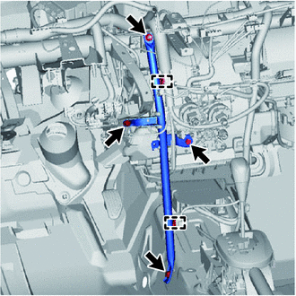
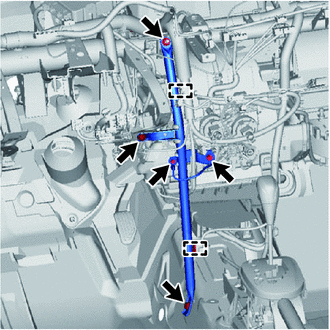
REMOVE BOOSTER VACUUM TUBE (for 1ND-TV)
-
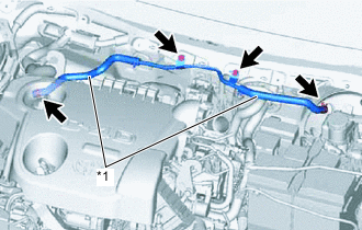
*1 Vacuum Hose Slide the 2 clips and disconnect the 2 vacuum hoses.
-
Remove the 2 bolts and the booster vacuum tube.
-
-
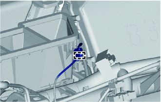
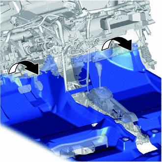
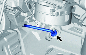
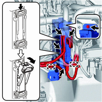
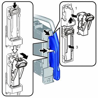
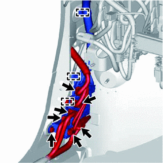
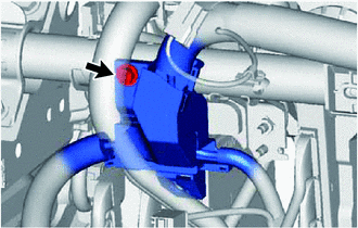
DISCONNECT SUCTION TUBE SUB-ASSEMBLY B
-
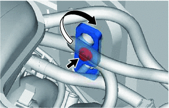
Remove the bolt.
-
Turn the hook connector clockwise and disconnect the suction tube sub-assembly B.
-
Remove the O-ring from the suction tube sub-assembly B.
Note
Seal the openings of the disconnected parts using vinyl tape to prevent the entry of moisture and foreign matter.
-
-
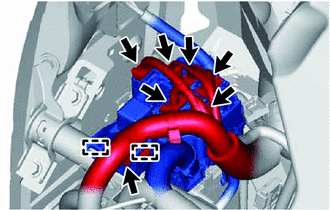
DISCONNECT LIQUID TUBE SUB-ASSEMBLY A
-
Disconnect the liquid tube sub-assembly A.
-
Remove the O-ring from the liquid tube sub-assembly A.
Note
Seal the opening of the disconnected parts using vinyl tape to prevent the entry of moisture and foreign matter.
-
-
REMOVE FUEL FILTER ASSEMBLY WITH SUPPORT (for 1ND-TV)
-
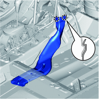
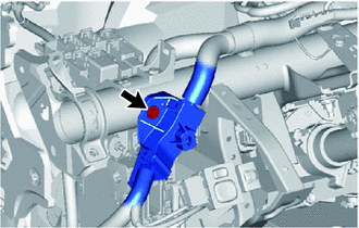
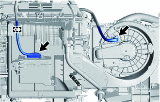
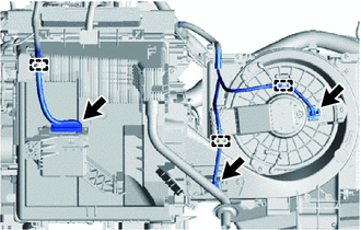
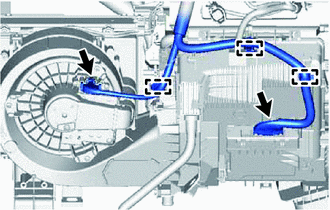
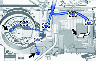
DISCONNECT WATER HOSE SUB-ASSEMBLY B
-
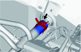
Slide the clip and disconnect the water hose sub-assembly B from the air conditioning unit.
-
-
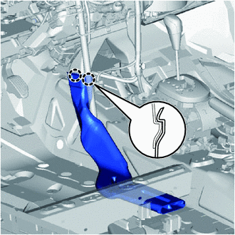
DISCONNECT WATER HOSE SUB-ASSEMBLY
-
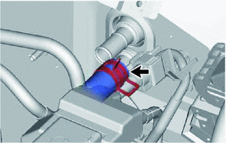
Slide the clip and disconnect the water hose sub-assembly from the air conditioning unit.
-
-
REMOVE LOWER INSTRUMENT PANEL SUB-ASSEMBLY
-
REMOVE STEERING COLUMN ASSEMBLY (for LHD)
-
REMOVE STEERING COLUMN ASSEMBLY (for RHD)
-
REMOVE HEATER TO REGISTER DUCT ASSEMBLY (w/ Navigation System)
-
Disengage the clamp and disconnect the wire harness.
-
Disengage the 3 claws and remove the heater to register duct assembly.
-
-
REMOVE HEATER TO REGISTER DUCT ASSEMBLY (w/o Navigation System)
-
Disengage the 3 claws and remove the heater to register duct assembly.
-
-
REMOVE NAVIGATION ANTENNA ASSEMBLY (w/ Navigation System)
-
REMOVE DEFROSTER NOZZLE ASSEMBLY
-
Disconnect the connectors and disengage the clamps, then disconnect the wire harness.
-
Disengage the 2 claws and 3 guides and remove the defroster nozzle assembly.
-
-
REMOVE REAR NO. 2 AIR DUCT (for Cold Area Specification Vehicles)
-
Open the floor carpet so that the rear No. 2 air duct can be removed and installed from the vehicle.
-
Disengage the 2 claws and remove the rear No. 2 air duct.
-
-
REMOVE REAR NO. 4 AIR DUCT (for Cold Area Specification Vehicles)
-
Disengage the 2 claws and remove the rear No. 4 air duct.
-
-
REMOVE REAR NO. 3 AIR DUCT (for Cold Area Specification Vehicles)
-
Disengage the 2 claws and remove the rear No. 3 air duct.
-
-
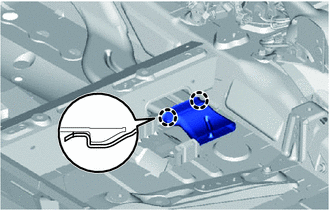
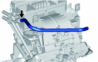
SEPARATE DRAIN COOLER HOSE
-
Separate the drain cooler hose.
-
-
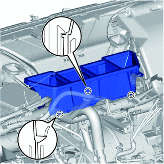
REMOVE NO. 1 INSTRUMENT PANEL BRACE SUB-ASSEMBLY (except Cold Area Specification Vehicles)
-
Disengage the 2 clamps.
-
Remove the 2 bolts, nut and screw, then remove the instrument panel brace sub-assembly.
-
-
REMOVE NO. 1 INSTRUMENT PANEL BRACE SUB-ASSEMBLY (for Cold Area Specification Vehicles)
-
Disengage the 2 clamps.
-
Remove the bolt and disconnect the ground wire.
-
Remove the 2 bolts, nut and screw, then remove the instrument panel brace sub-assembly.
-
-
REMOVE REAR NO. 1 AIR DUCT (for Cold Area Specification Vehicles)
-
Disengage the 2 claws and remove the rear No. 1 air duct.
-
-
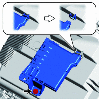
REMOVE INSTRUMENT PANEL JUNCTION BLOCK ASSEMBLY
-
Disengage the clamps.
-
Disconnect the connectors on the front side.
-
Remove the bolt and separate the instrument panel junction block assembly.
-
Disconnect the back side connectors and remove the instrument panel junction block assembly as shown in the illustration.
-
-
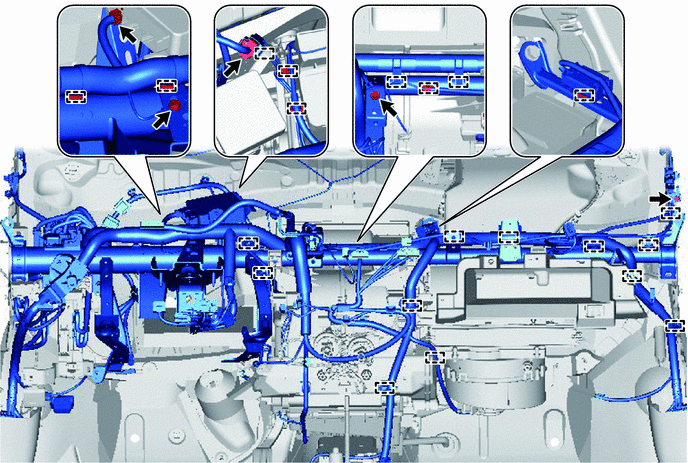
SEPARATE INSTRUMENT PANEL WIRE (for LHD)
-
Disconnect the connectors.
-
Remove the screw.
-
Disengage the 2 clamps and separate the connector holder.
-
Remove the screw and the connector holder.
-
Disconnect the connectors.
-
Remove the bolt.
-
Disengage the 3 clamps and remove the connector holder.
-
for Automatic Air Conditioning System:
-
Disconnect the 2 connectors.
-
Disengage the clamp and disconnect the instrument panel wire.
-
-
for Manual Air Conditioning System:
-
Disconnect the 3 connectors.
-
Disengage the 3 clamps and disconnect the instrument panel wire.
-
-
Remove the bolts and disconnect the ground wire.
-
Disconnect the connectors and clamps, then disconnect the instrument panel wire.
-
-
SEPARATE INSTRUMENT PANEL WIRE (for RHD)
-
Disconnect the connectors.
-
Remove the screw.
-
Disengage the 2 clamps and separate the connector holder.
-
Remove the screw and the connector holder.
-
Disconnect the connectors.
-
Remove the bolt.
-
Disengage the 3 clamps and remove the connector holder.
-
for Automatic Air Conditioning System:
-
Disconnect the 2 connectors.
-
Disengage the 3 clamps and disconnect the instrument panel wire.
-
-
for Manual Air Conditioning System:
-
Disconnect the 3 connectors.
-
Disengage the 5 clamps and disconnect the instrument panel wire.
-
-
Remove the bolts and disconnect the ground wire.
-
Disconnect the connectors and clamps, then disconnect the instrument panel wire.
-
-
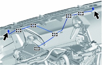
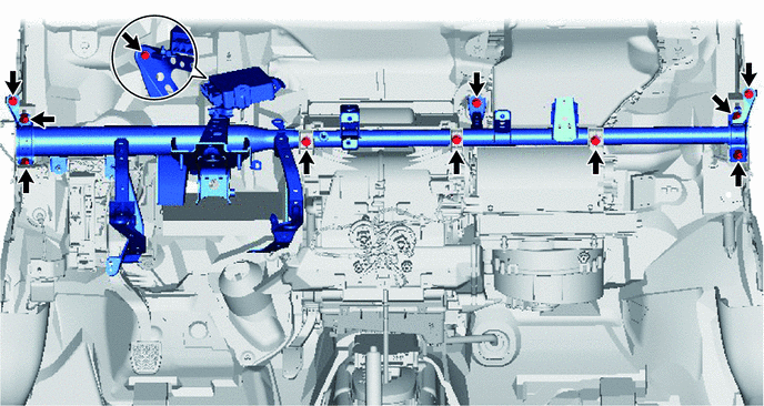
REMOVE INSTRUMENT PANEL REINFORCEMENT
-
Remove the 8 bolts and 3 screws, then remove the instrument panel reinforcement.
-
-
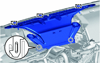
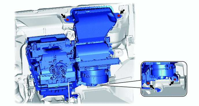
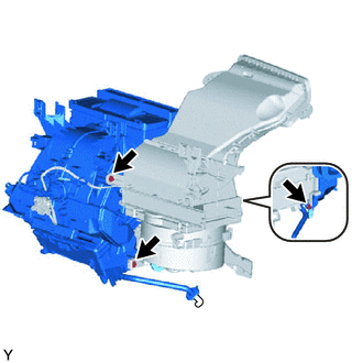
REMOVE AIR CONDITIONER UNIT ASSEMBLY
-
Remove the 3 bolts and nut, then remove the air conditioner unit assembly.
-
-
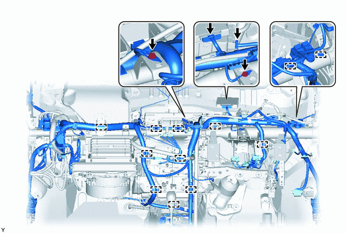
REMOVE AIR CONDITIONING HARNESS ASSEMBLY (for LHD)
-
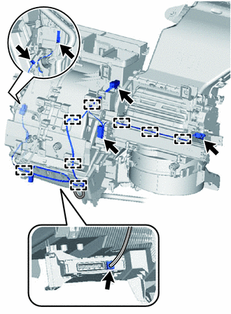
Disconnect the connectors and disengage the clamps, then remove the air conditioning harness assembly.
-
-
REMOVE AIR CONDITIONING HARNESS ASSEMBLY (for RHD)
-
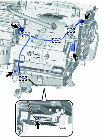
Disconnect the connectors and disengage the clamps, then remove the air conditioning harness assembly.
-
-
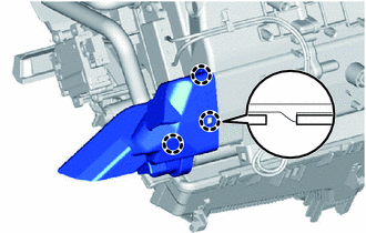
REMOVE AIR CONDITIONING AMPLIFIER ASSEMBLY (for Automatic Air Conditioning System)
-
Disconnect the connector.
-
Remove the screw.
-
Disengage the claw and remove the air conditioning amplifier assembly as shown in the illustration.
-
-
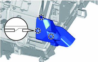
REMOVE AIR CONDITIONING AMPLIFIER ASSEMBLY (for Manual Air Conditioning System)
-
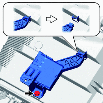
Remove the screw.
-
Disengage the claw and remove the air conditioning amplifier assembly as shown in the illustration.
-
-
REMOVE AIR CONDITIONING RADIATOR ASSEMBLY
-
Remove the 3 screws and the air conditioning radiator assembly.
-
-
REMOVE COOLER AIR HOSE (for Automatic Air Conditioning System)
-
Remove the cooler air hose.
-
-
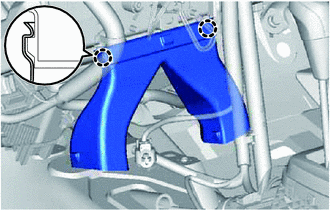
REMOVE NO. 1 AIR DUCT
-
Disengage the 3 claws and remove the No. 1 air duct.
-
-
REMOVE NO. 2 AIR DUCT
-
Disengage the 3 claws and remove the No. 2 air duct.
-