COMBUSTION TYPE POWER HEATER SYSTEM Power Heater Fuel Pump Circuit
DESCRIPTION
When the heater switch assembly is turned on, the heater pump assembly receives a drive voltage from the power heater ECU (combustion heater assembly). The heater pump assembly provides the combustion heater with fuel necessary for combustion, allowing the combustion heater to operate.
WIRING DIAGRAM
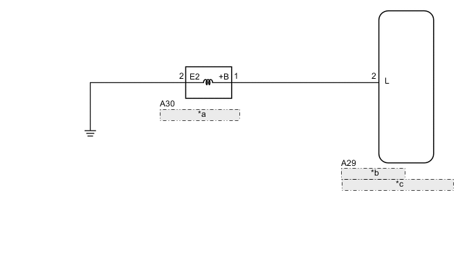
| *a | Heater Pump Assembly |
| *b | Power Heater ECU |
| *c | (Combustion Heater Assembly) |
PROCEDURE
-
INSPECT HEATER PUMP ASSEMBLY
-
Inspect the heater pump assembly Click here.
NG 
REPLACE HEATER PUMP ASSEMBLY Click here
OK 
-
-
CHECK HARNESS AND CONNECTOR (POWER HEATER ECU (COMBUSTION HEATER ASSEMBLY) - HEATER PUMP ASSEMBLY)
-
Disconnect the A29 power heater ECU (combustion heater assembly) connector.
-
Disconnect the A30 heater pump assembly connector.
-
Measure the resistance according to the value(s) in the table below.
Standard Resistance Tester Connection Condition Specified Condition A29-2 (L) - A30-1 (+B) Always Below 1 Ω A29-2 (L) - Body ground Always 10 kΩ or higher
NG
REPAIR OR REPLACE HARNESS OR CONNECTOR
OK
-
-
CHECK HARNESS AND CONNECTOR (HEATER PUMP ASSEMBLY - BODY GROUND)
-
Disconnect the A30 heater pump assembly connector.
-
Measure the resistance according to the value(s) in the table below.
Standard Resistance Tester Connection Condition Specified Condition A30-2 (E2) - Body ground Always Below 1 Ω
OK
PROCEED TO NEXT SUSPECTED AREA SHOWN IN PROBLEM SYMPTOMS TABLE Click here
NG
REPAIR OR REPLACE HARNESS OR CONNECTOR
-