COMBUSTION TYPE POWER HEATER SYSTEM DIAGNOSIS SYSTEM
Note
The cause of failures (such as abnormal voltage, overheating, a short-circuit, breakage of functional components, etc.) and repair methods can be checked by connecting the DTC tester and reading DTCs.
-
DTC CHECK/CLEAR
-
Turn the ignition switch off.
-
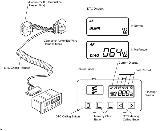
Disconnect the A29 power heater ECU (combustion heater assembly) connector.
-
Connect connector A of the DTC tester to the vehicle wire harness.
-
Connect connector B of the DTC tester to the combustion heater connector.
-
Start the engine.
-
Read the DTCs:
-
Pressing the DTC calling button displays a 3-digit number DTC.
-
-
Clear the DTCs:
-
Press both memory clear buttons together for more than 2 seconds.
-
-
-
DESCRIPTION OF THE DTC TESTER
Tech Tips
The DTC tester is able to store up to 5 DTCs in memory. The current DTC is shown as "AF" and a 3-digit number and always written in memory place F1. Previous DTCs are transferred to memory places F2 to F5, and the data in F5 is overwritten.
Item Description AF Current Malfunction (Blinking in the event of a current malfunction) DIAG DTC (Example: 064 Flame sensor malfunction) DTC Calling Button Read the DTC. Memory Clear Buttons Clear the DTC memory. DTC Memory Calling Button (<) Scrolls down the DTC memory (F5 - F1). DTC Memory Calling Button (>) Scrolls up the DTC memory (F1 - F5).