AIR CONDITIONING SYSTEM(for Manual Air Conditioning System) Headlight Signal Circuit
DESCRIPTION
The air conditioning amplifier assembly receives headlight operational signals to determine electrical load conditions. The electrical load condition signals are used for controlling the number of the PTC heater elements to be heated.
WIRING DIAGRAM
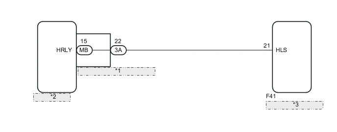
| *1 | Instrument Panel Junction Block Assembly |
| *2 | Main Body ECU |
| *3 | Air Conditioning Amplifier Assembly |
PROCEDURE
-
INSPECT HEADLIGHT ASSEMBLY
-
Check that the headlight comes on when the light control switch is turned to the HEAD position.
OK The headlight comes on.
NG 
GO TO LIGHTING SYSTEM Click here
OK 
-
-
CHECK HARNESS AND CONNECTOR (INSTRUMENT PANEL JUNCTION BLOCK ASSEMBLY - AIR CONDITIONING AMPLIFIER ASSEMBLY)
-
Disconnect the 3A instrument panel junction block assembly connector.
-
Disconnect the F41 air conditioning amplifier assembly connector.
-
Measure the resistance according to the value(s) in the table below.
Standard Resistance Tester Connection Condition Specified Condition 3A-22 - F41-21 (HLS) Always Below 1 Ω 3A-22 - Body ground Always 10 kΩ or higher
NG
REPAIR OR REPLACE HARNESS OR CONNECTOR
OK
-
-
INSPECT INSTRUMENT PANEL JUNCTION BLOCK ASSEMBLY
-
Remove the instrument panel junction block assembly.
-
Remove the main body ECU from the instrument panel junction block assembly.
-
Measure the resistance according to the value(s) in the table below.
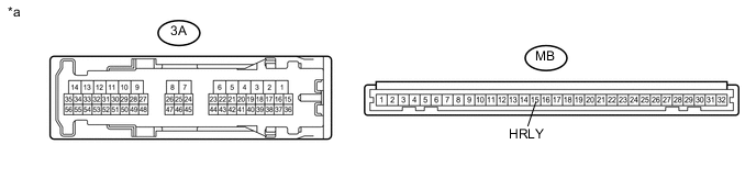
Text in Illustration *a Component without harness connected
(Instrument Panel Junction Block Assembly)
- - Standard Resistance Tester Connection Condition Specified Condition 3A-22 - MB-15 (HRLY) Always Below 1 Ω
OK
PROCEED TO NEXT SUSPECTED AREA SHOWN IN PROBLEM SYMPTOMS TABLE Click here
NG
REPLACE INSTRUMENT PANEL JUNCTION BLOCK ASSEMBLY
-